How to Use 128x64 OLED Display (I2C IIC SPI Serial): Examples, Pinouts, and Specs
Introduction
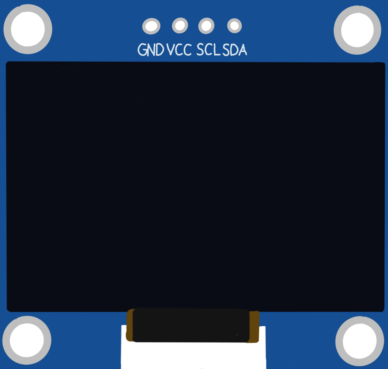
The DollaTek 128x64 OLED Display is a compact and versatile screen module that utilizes organic light-emitting diodes to provide a high-contrast, high-resolution display. This particular model, identified by the part ID SSH1106, is capable of displaying graphics and text in a monochrome (single-color) format. It supports multiple communication protocols, including I2C (Inter-Integrated Circuit), IIC (Intelligent Interface Controller, often used interchangeably with I2C), and SPI (Serial Peripheral Interface), making it highly adaptable to various microcontroller platforms, such as Arduino, Raspberry Pi, and others.
Explore Projects Built with 128x64 OLED Display (I2C IIC SPI Serial)


Explore Projects Built with 128x64 OLED Display (I2C IIC SPI Serial)
Common Applications and Use Cases
- User interfaces for embedded systems
- Display for IoT devices
- Real-time data monitoring screens
- Portable instrument readouts
- DIY electronics projects
Technical Specifications
Key Technical Details
- Resolution: 128x64 pixels
- Color: Monochrome (White/Blue)
- Viewing Angle: >160 degrees
- Operating Voltage: 3.3V to 5V
- Communication Protocols: I2C/IIC, SPI
- Driver IC: SSH1106
Pin Configuration and Descriptions
| Pin Number | I2C/IIC Mode | SPI Mode | Description |
|---|---|---|---|
| 1 | GND | GND | Ground |
| 2 | VCC | VCC | Power Supply (3.3V-5V) |
| 3 | SCL | D0/CLK | Serial Clock Line |
| 4 | SDA | D1/MOSI | Serial Data Line |
| 5 | RES | RES | Reset Pin |
| 6 | DC | DC | Data/Command Control Pin |
| 7 | CS | CS | Chip Select (SPI mode) |
| 8 | - | - | Not Connected |
Usage Instructions
How to Use the Component in a Circuit
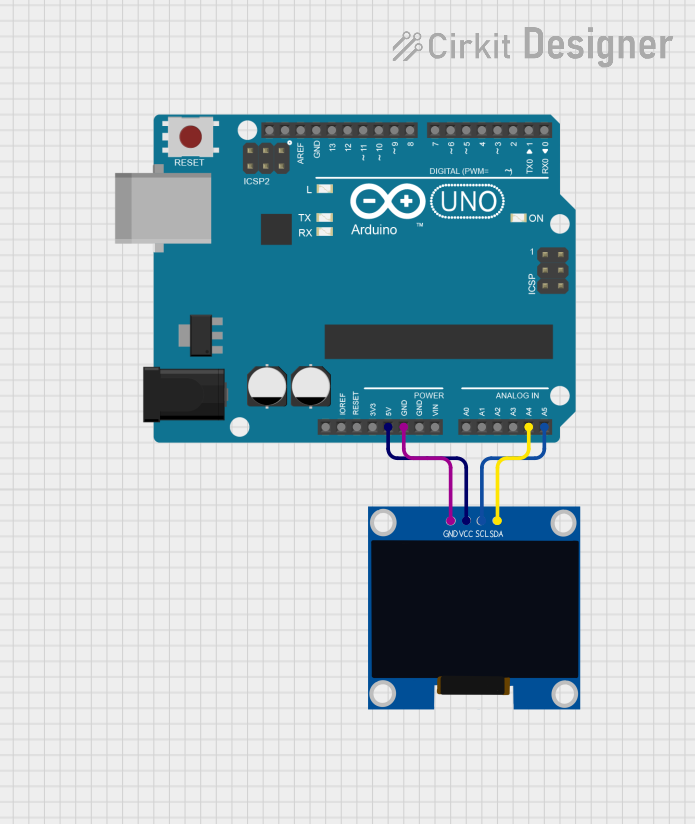
- Power Connections: Connect the VCC pin to a 3.3V or 5V power supply and the GND pin to the ground.
- Data Connections (I2C/IIC Mode): Connect the SCL pin to the I2C clock line and the SDA pin to the I2C data line of your microcontroller.
- Data Connections (SPI Mode): Connect D0/CLK to the SPI clock, D1/MOSI to the SPI MOSI line, CS to the chip select, DC to the data/command control pin, and RES to the reset pin of your microcontroller.
- Initialization: Upon power-up, the display must be initialized using the appropriate commands sent from the microcontroller.
Important Considerations and Best Practices
- Ensure that the power supply voltage matches the operating voltage of the display to prevent damage.
- Use pull-up resistors on the I2C data lines if your microcontroller does not have built-in pull-ups.
- In SPI mode, ensure that the CS pin is toggled appropriately to enable and disable the display during communication.
- The RES pin can be used to reset the display. It is typically pulled high and can be momentarily pulled low to reset the display.
Example Code for Arduino UNO (I2C Mode)
#include <Wire.h>
#include <Adafruit_GFX.h>
#include <Adafruit_SSD1306.h>

#define SCREEN_WIDTH 128 // OLED display width, in pixels
#define SCREEN_HEIGHT 64 // OLED display height, in pixels

// Declaration for an SSD1306 display connected to I2C (SDA, SCL pins)
#define OLED_RESET     -1 // Reset pin # (or -1 if sharing Arduino reset pin)
Adafruit_SSD1306 display(SCREEN_WIDTH, SCREEN_HEIGHT, &Wire, OLED_RESET);

void setup() {
  // Initialize with the I2C addr 0x3C (for the 128x64)
  if(!display.begin(SSD1306_SWITCHCAPVCC, 0x3C)) {
    Serial.println(F("SSD1306 allocation failed"));
    for(;;); // Don't proceed, loop forever
  }

  // Clear the buffer
  display.clearDisplay();

  // Draw a single pixel in white
  display.drawPixel(10, 10, WHITE);

  // Display the drawing
  display.display();
}

void loop() {
  // Nothing here for this simple example
}
Note: The example code provided uses the Adafruit SSD1306 library, which is compatible with the SSH1106 driver with minor differences. The library can be installed via the Arduino Library Manager.
Troubleshooting and FAQs
Common Issues Users Might Face
- Display Not Powering On: Check the power connections and ensure the voltage is within the specified range.
- No Data on Display: Verify that the I2C/SPI connections are correct and that the correct communication protocol is selected.
- Garbled or Incomplete Data: Ensure that the display is properly initialized and that the correct resolution is set in the code.
Solutions and Tips for Troubleshooting
- Double-check wiring connections for any loose or incorrect connections.
- Use a multimeter to verify that the correct voltage is reaching the display.
- If using I2C, scan the I2C bus with a scanner sketch to ensure the display is detected.
- In the case of SPI, ensure that the CS, DC, and RES pins are being controlled correctly by the microcontroller.
FAQs
Q: Can I use this display with a 5V microcontroller? A: Yes, the display can be powered with 5V, but ensure that the logic levels for data lines match the microcontroller's.
Q: How do I know if my display is in I2C or SPI mode? A: The mode is determined by how you wire the display to your microcontroller and how you initialize it in your code.
Q: What library should I use for this display? A: For Arduino, the Adafruit SSD1306 library is commonly used, though you may need to make minor adjustments for the SSH1106 driver.
Q: Can I display images on this OLED? A: Yes, you can display bitmap images by converting them into a byte array format that the display can interpret.
Q: How do I adjust the contrast or brightness of the display? A: These settings can be adjusted through commands sent from the microcontroller to the display. Refer to the SSH1106 datasheet for specific commands.