How to Use WEMOS LOLIN32 OLED: Examples, Pinouts, and Specs

 Design with WEMOS LOLIN32 OLED in Cirkit Designer
Introduction
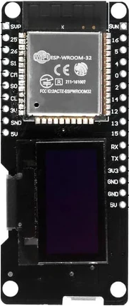
The WEMOS LOLIN32 OLED is a versatile and powerful development board that combines the advanced features of the ESP32 microcontroller with the convenience of an integrated OLED display. This board is ideal for IoT projects, wearable devices, and any application where visual feedback is beneficial. With built-in Wi-Fi and Bluetooth capabilities, the WEMOS LOLIN32 OLED is perfect for creating connected devices.
Explore Projects Built with WEMOS LOLIN32 OLED

 Open Project in Cirkit Designer
 Open Project in Cirkit Designer
 Open Project in Cirkit Designer
 Open Project in Cirkit Designer
Explore Projects Built with WEMOS LOLIN32 OLED

 Open Project in Cirkit Designer
 Open Project in Cirkit Designer
 Open Project in Cirkit Designer
 Open Project in Cirkit Designer
Common Applications and Use Cases
- Internet of Things (IoT) devices
- Wearable technology
- Home automation systems
- Prototyping for embedded systems
- DIY electronics projects
- Data monitoring and visualization
Technical Specifications
Key Technical Details
- Microcontroller: ESP32
- Operating Voltage: 3.3V
- Input Voltage (recommended): 5V via micro USB
- Digital I/O Pins: 26
- Analog Input Pins: 12
- Flash Memory: 4MB
- SRAM: 520 KB
- Clock Speed: 240 MHz
- Wi-Fi: 802.11 b/g/n
- Bluetooth: v4.2 BR/EDR and BLE
- OLED Display: 0.96 inch, 128x64 pixels, SSD1306 driver
Pin Configuration and Descriptions
| Pin Number | Function | Description |
|---|---|---|
| 1 | GND | Ground |
| 2 | 3V3 | 3.3V power supply |
| 3 | EN | Reset pin, active low |
| 4 | VP | 36, ADC, Capacitive touch |
| 5 | VN | 39, ADC, Capacitive touch |
| 6 | IO34 | 34, ADC |
| 7 | IO35 | 35, ADC |
| 8 | IO32 | 32, ADC, DAC, Capacitive touch |
| 9 | IO33 | 33, ADC, DAC, Capacitive touch |
| 10 | IO25 | 25, ADC, DAC |
| 11 | IO26 | 26, ADC, DAC |
| 12 | IO27 | 27, ADC, Capacitive touch |
| 13 | IO14 | 14, ADC, Capacitive touch, SPI |
| 14 | IO12 | 12, ADC, Capacitive touch, SPI |
| 15 | IO13 | 13, ADC, Capacitive touch, SPI |
| 16 | IO9 | 9, SPI |
| 17 | IO10 | 10, SPI |
| 18 | IO11 | 11, SPI |
| 19 | IO6 | 6, SPI |
| 20 | IO7 | 7, SPI |
| 21 | IO8 | 8, SPI |
| 22 | IO23 | 23, SPI |
| 23 | IO22 | 22, I2C |
| 24 | TX0 | UART |
| 25 | RX0 | UART |
| 26 | IO5 | 5, SPI |
| 27 | IO18 | 18, SPI |
| 28 | IO19 | 19, SPI |
| 29 | IO21 | 21, I2C |
| 30 | GND | Ground |
| 31 | 5V | 5V power supply via USB |
Usage Instructions
How to Use the Component in a Circuit
Powering the Board:
- Connect the micro USB cable to the board and your computer or a 5V USB power source.
- Ensure that the input voltage does not exceed the recommended 5V.
Connecting to the OLED Display:
- The OLED display is built-in and requires no additional wiring.
- The display is controlled via the I2C interface, typically using GPIO pins 4 (SDA) and 15 (SCL).
Programming the Board:
- Install the latest version of the Arduino IDE.
- Install the ESP32 board package using the Board Manager.
- Select the appropriate board and port in the Arduino IDE.
- Write your sketch and upload it to the board.
Important Considerations and Best Practices
- Always disconnect the board from power sources before making or altering connections.
- Use a current limiting resistor when connecting LEDs to GPIO pins to prevent damage.
- Avoid exposing the board to static electricity or physical stress.
- Ensure that the board's antenna is not obstructed for optimal wireless performance.
Troubleshooting and FAQs
Common Issues Users Might Face
Board not recognized by the computer:
- Check the micro USB cable and the USB port.
- Ensure that the correct drivers are installed.
OLED display not working:
- Verify that the OLED library is correctly installed and configured.
- Check the I2C connections and ensure that the correct pins are used in the code.
Difficulty uploading sketches:
- Ensure that the correct board and port are selected in the Arduino IDE.
- Hold down the "BOOT" button on the board when starting the upload process.
Solutions and Tips for Troubleshooting
- If the board is not recognized, try using a different USB cable or port.
- For OLED issues, double-check the library examples and compare them with your code.
- When uploading sketches, make sure no other programs are using the COM port.
Example Code for Arduino UNO
#include <Wire.h>
#include <Adafruit_GFX.h>
#include <Adafruit_SSD1306.h>

// OLED display TWI address
#define OLED_ADDR   0x3C
// Reset pin not used on 4-pin OLED module
Adafruit_SSD1306 display(-1);

// Initialize with the I2C addr 0x3C (for the 128x64)
// Always reset the display at the beginning
void setup() {
  Wire.begin(5, 4); // Initialize I2C
  display.begin(SSD1306_SWITCHCAPVCC, OLED_ADDR);
  display.display();
  delay(2000); // Pause for 2 seconds
  display.clearDisplay();
}

void loop() {
  display.setTextSize(1);
  display.setTextColor(WHITE);
  display.setCursor(0,0);
  display.println(F("Hello, world!"));
  display.display();
  delay(2000);
  display.clearDisplay();
}
Note: This example assumes the use of the Adafruit SSD1306 library for the OLED display. Ensure that the library is installed in the Arduino IDE before compiling and uploading the sketch. The I2C pins are defined as GPIO 5 (SDA) and GPIO 4 (SCL) in the Wire.begin(5, 4); statement. Adjust these pin numbers if your board uses different pins for I2C communication.