How to Use ponte H L9110: Examples, Pinouts, and Specs
Introduction
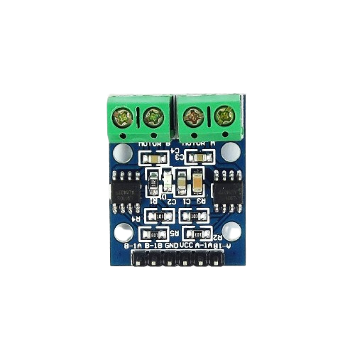
The L9110 H-Bridge is a dual-channel motor driver designed for controlling DC motors and stepper motors. It enables bidirectional control of motors, allowing them to rotate in both forward and reverse directions. Compact and efficient, the L9110 is widely used in robotics, automation systems, and other motor control applications. Its simplicity and low power consumption make it an excellent choice for hobbyists and professionals alike.
Explore Projects Built with ponte H L9110
Explore Projects Built with ponte H L9110
Common Applications:
- Robotics (e.g., controlling robot wheels)
- Automation systems
- DIY motorized projects
- Stepper motor control
- Small-scale conveyor systems
Technical Specifications
Below are the key technical details of the L9110 H-Bridge motor driver:
| Parameter | Value |
|---|---|
| Operating Voltage | 2.5V to 12V |
| Output Current (per channel) | 800mA (continuous) |
| Peak Output Current | 1.5A |
| Number of Channels | 2 |
| Logic Input Voltage | 0V to 5V |
| Control Logic | TTL/CMOS compatible |
| Operating Temperature | -40°C to +85°C |
| Dimensions | Approx. 29mm x 23mm x 5mm |
Pin Configuration and Descriptions
The L9110 module typically has the following pin layout:
| Pin Name | Description |
|---|---|
VCC |
Power supply input (2.5V to 12V). Connect to the positive terminal of the power source. |
GND |
Ground. Connect to the negative terminal of the power source. |
A-IA |
Input A control signal. Used to control the direction of Motor A. |
A-IB |
Input B control signal. Used to control the direction of Motor A. |
B-IA |
Input A control signal. Used to control the direction of Motor B. |
B-IB |
Input B control signal. Used to control the direction of Motor B. |
Motor A |
Output terminals for Motor A. Connect the two wires of Motor A here. |
Motor B |
Output terminals for Motor B. Connect the two wires of Motor B here. |
Usage Instructions
How to Use the L9110 in a Circuit
- Power Supply: Connect the
VCCpin to a power source (2.5V to 12V) and theGNDpin to ground. - Motor Connections: Attach the two wires of Motor A to the
Motor Aoutput terminals and Motor B to theMotor Boutput terminals. - Control Signals: Use the
A-IA,A-IB,B-IA, andB-IBpins to control the direction and speed of the motors:- Set one input HIGH and the other LOW to rotate the motor in one direction.
- Reverse the HIGH and LOW signals to rotate the motor in the opposite direction.
- Set both inputs LOW to stop the motor.
Example: Connecting to an Arduino UNO
Below is an example of how to control two DC motors using the L9110 and an Arduino UNO:
Circuit Connections:
- Connect
VCCto the Arduino's 5V pin. - Connect
GNDto the Arduino's GND pin. - Connect
A-IAto Arduino pin 9 andA-IBto pin 10. - Connect
B-IAto Arduino pin 6 andB-IBto pin 7. - Connect the motors to the
Motor AandMotor Bterminals.
Arduino Code:
// Define motor control pins
const int motorA_IA = 9;  // Motor A Input A
const int motorA_IB = 10; // Motor A Input B
const int motorB_IA = 6;  // Motor B Input A
const int motorB_IB = 7;  // Motor B Input B

void setup() {
  // Set motor control pins as outputs
  pinMode(motorA_IA, OUTPUT);
  pinMode(motorA_IB, OUTPUT);
  pinMode(motorB_IA, OUTPUT);
  pinMode(motorB_IB, OUTPUT);
}

void loop() {
  // Rotate Motor A forward
  digitalWrite(motorA_IA, HIGH);
  digitalWrite(motorA_IB, LOW);

  // Rotate Motor B backward
  digitalWrite(motorB_IA, LOW);
  digitalWrite(motorB_IB, HIGH);

  delay(2000); // Run motors for 2 seconds

  // Stop both motors
  digitalWrite(motorA_IA, LOW);
  digitalWrite(motorA_IB, LOW);
  digitalWrite(motorB_IA, LOW);
  digitalWrite(motorB_IB, LOW);

  delay(2000); // Wait for 2 seconds

  // Rotate Motor A backward
  digitalWrite(motorA_IA, LOW);
  digitalWrite(motorA_IB, HIGH);

  // Rotate Motor B forward
  digitalWrite(motorB_IA, HIGH);
  digitalWrite(motorB_IB, LOW);

  delay(2000); // Run motors for 2 seconds

  // Stop both motors
  digitalWrite(motorA_IA, LOW);
  digitalWrite(motorA_IB, LOW);
  digitalWrite(motorB_IA, LOW);
  digitalWrite(motorB_IB, LOW);

  delay(2000); // Wait for 2 seconds
}
Important Considerations:
- Ensure the power supply voltage matches the motor's operating voltage.
- Avoid exceeding the maximum current rating (800mA per channel) to prevent damage.
- Use proper heat dissipation if operating at high currents for extended periods.
Troubleshooting and FAQs
Common Issues and Solutions:
Motors Not Spinning:
- Verify the power supply connection to the
VCCandGNDpins. - Check the control signal connections to the input pins (
A-IA,A-IB,B-IA,B-IB). - Ensure the motor wires are securely connected to the output terminals.
- Verify the power supply connection to the
Motor Spins in Only One Direction:
- Check the logic levels of the input pins. Ensure one pin is HIGH and the other is LOW.
- Verify the Arduino code for correct pin assignments.
Overheating:
- Ensure the current drawn by the motors does not exceed 800mA per channel.
- Use a heat sink or cooling mechanism if necessary.
No Response from the Module:
- Confirm that the module is receiving the correct operating voltage.
- Inspect for any loose or damaged connections.
FAQs:
Q: Can the L9110 drive stepper motors?
A: Yes, the L9110 can control stepper motors by driving the two channels in a coordinated manner. However, additional logic or a library may be required for precise stepper motor control.
Q: Can I use the L9110 with a 3.3V microcontroller?
A: Yes, the L9110 is compatible with 3.3V logic levels, but ensure the motor's power supply voltage is within the module's operating range.
Q: What is the maximum motor voltage supported?
A: The L9110 supports motor voltages up to 12V.
By following this documentation, you can effectively use the L9110 H-Bridge motor driver in your projects!