How to Use Tic Controller: Examples, Pinouts, and Specs
Introduction
The Pololu Tic T825 is a versatile and programmable stepper motor controller designed to simplify the control of stepper motors in a wide range of applications. It integrates advanced features such as USB, TTL serial, and I²C interfaces, making it suitable for both standalone and microcontroller-based systems. The Tic T825 is ideal for applications requiring precise motor control, such as robotics, 3D printers, CNC machines, and automated systems.
Explore Projects Built with Tic Controller

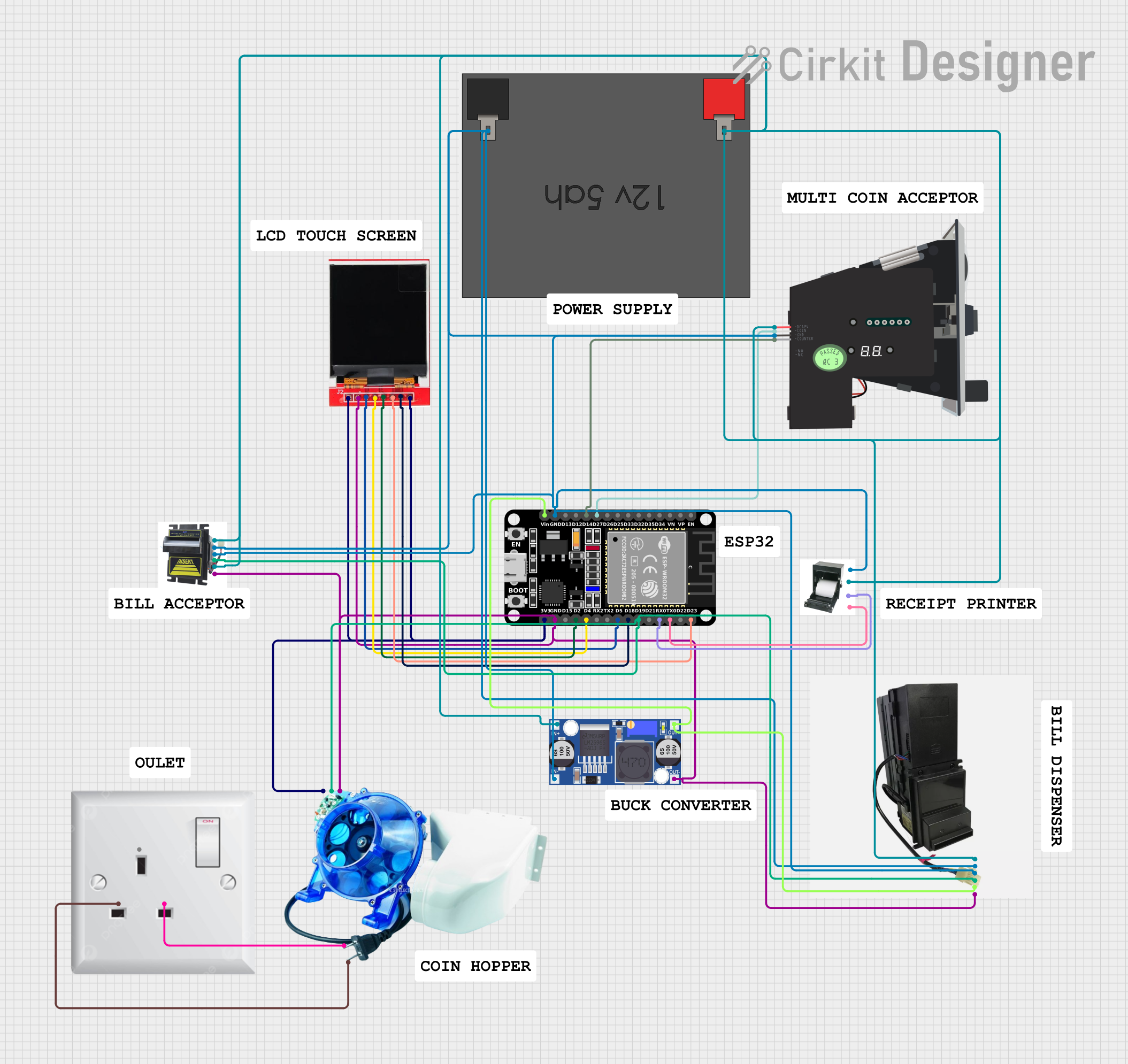
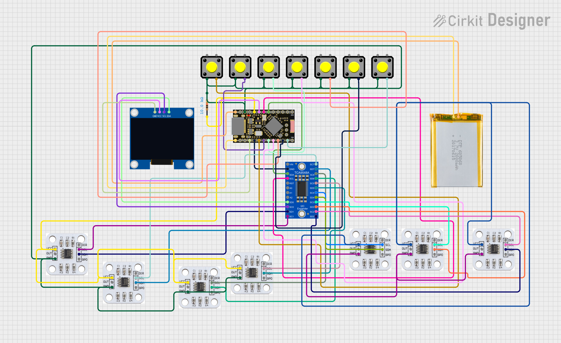
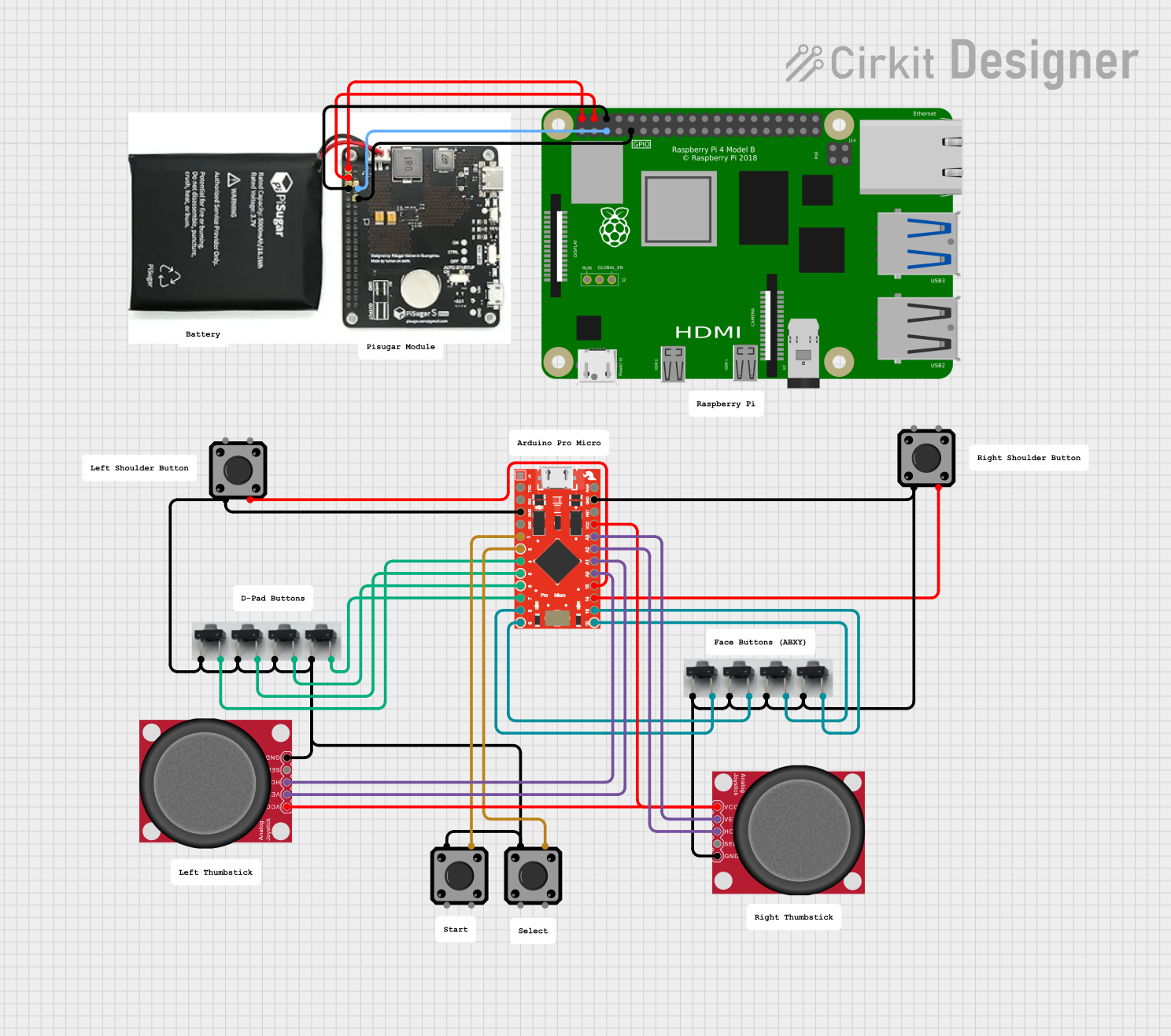
Explore Projects Built with Tic Controller
Technical Specifications
The following table outlines the key technical details of the Pololu Tic T825:
| Specification | Details |
|---|---|
| Input Voltage Range | 8 V to 45 V |
| Maximum Motor Current | 1.5 A per phase (continuous) or 2 A per phase (peak) |
| Control Interfaces | USB, TTL Serial, I²C, Analog Voltage, RC Pulse |
| Microstepping Modes | Full step, 1/2, 1/4, 1/8, 1/16, 1/32 |
| Logic Voltage | 3.3 V or 5 V (compatible with most microcontrollers) |
| Dimensions | 1.2" × 0.8" × 0.2" (30 mm × 20 mm × 5 mm) |
| Operating Temperature | -40°C to +85°C |
| Protection Features | Over-temperature, under-voltage, over-current, and short-circuit protection |
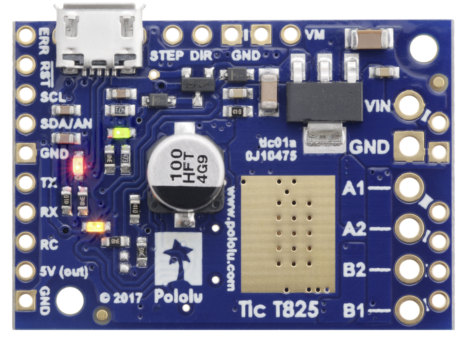
Pin Configuration and Descriptions
The Tic T825 has a compact design with the following pin layout:
| Pin Name | Type | Description |
|---|---|---|
| VIN | Power Input | Connect to the motor power supply (8 V to 45 V). |
| GND | Power Ground | Ground connection for the power supply and logic circuits. |
| A1, A2 | Motor Output | Connect to one coil of the stepper motor. |
| B1, B2 | Motor Output | Connect to the other coil of the stepper motor. |
| TX | TTL Serial | Transmit pin for serial communication. |
| RX | TTL Serial | Receive pin for serial communication. |
| SCL | I²C Clock | Clock line for I²C communication. |
| SDA | I²C Data | Data line for I²C communication. |
| RC | Input | Accepts RC pulse signals for control. |
| AN | Input | Accepts analog voltage for control. |
| USB | USB Interface | Connect to a computer for configuration or control via USB. |
| ERR | Output | Error indicator pin (active low). |
| RST | Input | Reset pin to restart the controller. |
Usage Instructions
How to Use the Tic T825 in a Circuit
- Power Supply: Connect a power supply (8 V to 45 V) to the VIN and GND pins. Ensure the power supply can provide sufficient current for your stepper motor.
- Motor Connection: Connect the stepper motor coils to the A1, A2, B1, and B2 pins. Refer to your motor's datasheet for the correct wiring.
- Control Interface: Choose a control method (USB, TTL serial, I²C, RC, or analog voltage) and connect the corresponding pins to your microcontroller or control device.
- Configuration: Use the Pololu Tic Control Center software to configure the controller via USB. Set parameters such as step mode, current limits, and control interface.
- Operation: Send commands to the Tic T825 using your chosen interface to control the stepper motor's speed, direction, and position.
Important Considerations and Best Practices
- Heat Dissipation: The Tic T825 can get warm during operation. Ensure adequate ventilation or use a heatsink if necessary.
- Current Limiting: Set the current limit in the Tic Control Center to match your motor's rated current to prevent overheating or damage.
- Power Supply: Use a stable and noise-free power supply to avoid erratic motor behavior.
- Wiring: Keep motor and power wires as short as possible to minimize electrical noise.
Example: Using the Tic T825 with an Arduino UNO
Below is an example of controlling the Tic T825 via TTL serial using an Arduino UNO:
#include <SoftwareSerial.h>

// Define Arduino pins for software serial communication
#define TX_PIN 10  // Arduino TX pin connected to Tic RX
#define RX_PIN 11  // Arduino RX pin connected to Tic TX

SoftwareSerial ticSerial(TX_PIN, RX_PIN);

void setup() {
  ticSerial.begin(9600); // Initialize serial communication with the Tic
  delay(100);            // Allow time for the Tic to initialize

  // Set the Tic to "Serial" control mode
  sendCommand(0x83); // Exit safe start
}

void loop() {
  // Example: Set target position to 2000 steps
  setTargetPosition(2000);
  delay(2000); // Wait for 2 seconds

  // Example: Set target position to -2000 steps
  setTargetPosition(-2000);
  delay(2000); // Wait for 2 seconds
}

// Function to send a command to the Tic
void sendCommand(uint8_t command) {
  ticSerial.write(command);
}

// Function to set the target position
void setTargetPosition(int32_t position) {
  ticSerial.write(0xE0); // Command byte for "Set target position"
  ticSerial.write((uint8_t)(position & 0xFF));       // Lowest byte
  ticSerial.write((uint8_t)((position >> 8) & 0xFF)); // 2nd byte
  ticSerial.write((uint8_t)((position >> 16) & 0xFF)); // 3rd byte
  ticSerial.write((uint8_t)((position >> 24) & 0xFF)); // Highest byte
}
Troubleshooting and FAQs
Common Issues and Solutions
Motor Not Moving:
- Ensure the motor is properly connected to the A1, A2, B1, and B2 pins.
- Verify that the power supply voltage is within the specified range (8 V to 45 V).
- Check the current limit setting in the Tic Control Center.
Overheating:
- Reduce the current limit to match the motor's rated current.
- Improve ventilation or add a heatsink to the controller.
Communication Errors:
- Verify the wiring between the Tic and the control device (e.g., Arduino).
- Ensure the baud rate and communication settings match on both devices.
Error Indicator Active:
- Check the ERR pin or the Tic Control Center for detailed error information.
- Resolve issues such as over-temperature, under-voltage, or over-current conditions.
FAQs
Can I use the Tic T825 with a 12 V power supply? Yes, the Tic T825 supports input voltages from 8 V to 45 V, so a 12 V power supply is suitable.
What stepper motors are compatible with the Tic T825? The Tic T825 is compatible with bipolar stepper motors that operate within the voltage and current limits of the controller.
How do I reset the Tic T825? You can reset the Tic T825 by briefly pulling the RST pin low or by using the reset option in the Tic Control Center software.
Can I control multiple Tic controllers with one Arduino? Yes, you can control multiple Tic controllers using unique addresses for I²C or separate serial connections.
This documentation provides a comprehensive guide to using the Pololu Tic T825 stepper motor controller. For additional details, refer to the official Pololu documentation.