How to Use MAX7219: Examples, Pinouts, and Specs

Introduction
The MAX7219 is a compact, serial input/output common-cathode display driver that can interface microcontrollers to 7-segment numeric LED displays of up to 8 digits, bar-graph displays, or 64 individual LEDs. It includes on-chip BCD code-B decoders, multiplex scan circuitry, segment and digit drivers, and an 8x8 static RAM to store each digit. The MAX7219 simplifies the process of controlling multiple LEDs in matrix or numeric display form. Common applications include digital clocks, electronic meters, and other electronic devices that require display of numerical information.
Explore Projects Built with MAX7219


Explore Projects Built with MAX7219
Technical Specifications
Key Technical Details
- Operating Voltage: 4.0V to 5.5V
- Maximum Current: 320mA when all segments are lit
- Display Scan Rate: 800Hz
- Serial Interface: SPI-compatible
- Operating Temperature: -40°C to +85°C
Pin Configuration and Descriptions
| Pin Number | Name | Description |
|---|---|---|
| 1 | DIG 0 | Digit 0 drive (active low) |
| 2 | DIG 1 | Digit 1 drive (active low) |
| 3 | DIG 2 | Digit 2 drive (active low) |
| 4 | DIG 3 | Digit 3 drive (active low) |
| 5 | DIG 4 | Digit 4 drive (active low) |
| 6 | DIG 5 | Digit 5 drive (active low) |
| 7 | DIG 6 | Digit 6 drive (active low) |
| 8 | DIG 7 | Digit 7 drive (active low) |
| 9 | GND | Ground |
| 10 | SEG D | Segment D drive |
| 11 | SEG E | Segment E drive |
| 12 | SEG F | Segment F drive |
| 13 | SEG G | Segment G drive |
| 14 | SEG DP | Decimal point drive |
| 15 | SEG C | Segment C drive |
| 16 | SEG B | Segment B drive |
| 17 | SEG A | Segment A drive |
| 18 | ISET | Current set for segments |
| 19 | V+ | Positive supply voltage |
| 20 | LOAD | Load data into the display driver |
| 21 | DIN | Serial-data input |
| 22 | CLK | Serial-clock input |
| 23 | DOUT | Serial-data output |
| 24 | CS | Chip select (active low) |
Usage Instructions
Interfacing with a Circuit
To use the MAX7219 in a circuit:
- Connect V+ to a 5V supply and GND to the system ground.
- Connect the ISET pin to a resistor that sets the segment current.
- Connect the individual LED segments or displays to the SEG and DIG pins.
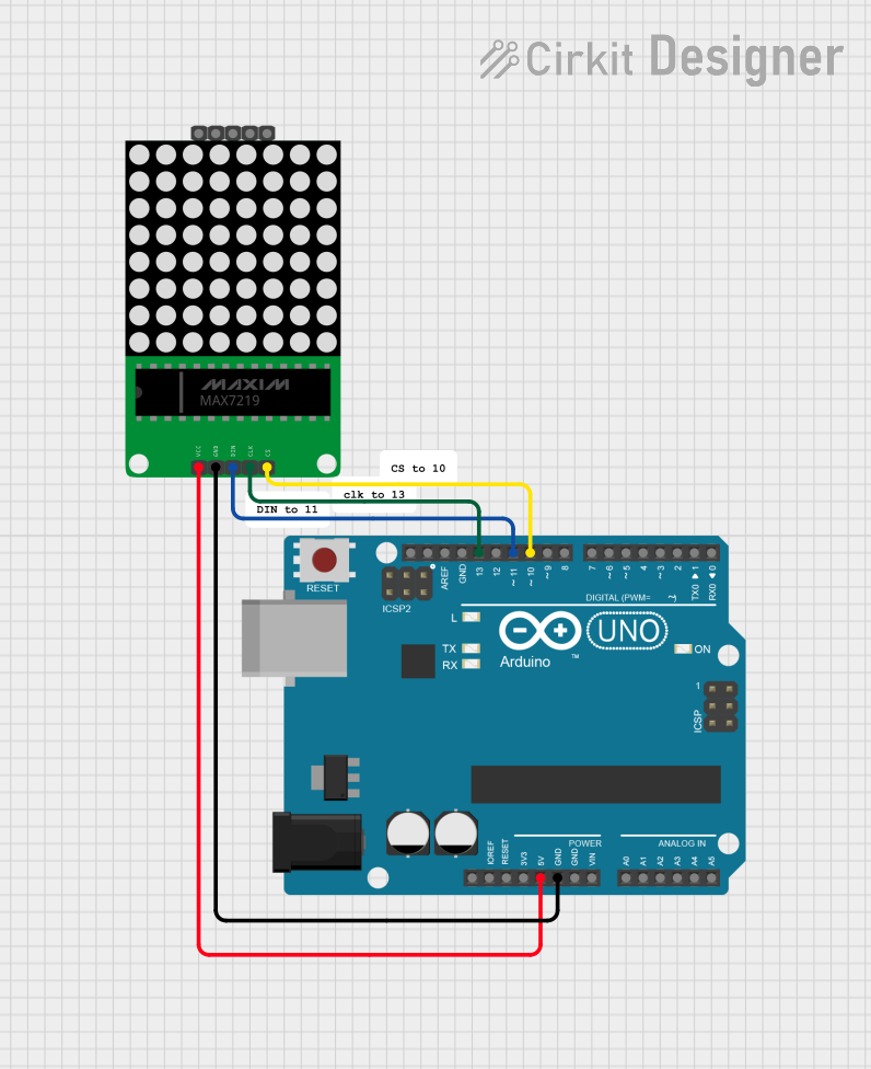
- Interface the LOAD, DIN, CLK, and CS pins to the microcontroller for SPI communication.
Best Practices
- Use a current-limiting resistor on the ISET pin to prevent excessive current through the LEDs.
- Ensure that the power supply can handle the maximum current required by the display.
- Keep the wiring between the MAX7219 and the LEDs as short as possible to minimize noise and voltage drop.
- Use bypass capacitors near the power supply pins to filter out noise.
Example Code for Arduino UNO
#include <SPI.h>

// Define the connections to the MAX7219
#define MAX7219_DIN   11
#define MAX7219_CS    10
#define MAX7219_CLK   13

// Define the number of digits in the display
#define NUM_DIGITS    8

// Initialize the MAX7219
void setup() {
  SPI.begin();
  pinMode(MAX7219_CS, OUTPUT);
  digitalWrite(MAX7219_CS, HIGH);
  sendCommand(0x0C, 0x01); // Turn on the display
  sendCommand(0x0B, NUM_DIGITS - 1); // Set scan limit
  sendCommand(0x09, 0xFF); // Enable mode B decode for all digits
  sendCommand(0x0A, 0x0F); // Set intensity (range is 0x00 to 0x0F)
  clearDisplay();
}

// Send a command to the MAX7219
void sendCommand(byte command, byte data) {
  digitalWrite(MAX7219_CS, LOW);
  SPI.transfer(command); // Send the command byte
  SPI.transfer(data);    // Send the data byte
  digitalWrite(MAX7219_CS, HIGH);
}

// Clear the display
void clearDisplay() {
  for (byte i = 0; i < NUM_DIGITS; i++) {
    sendCommand(i + 1, 0x0F);
  }
}

void loop() {
  // Your code to update the display goes here
}
Troubleshooting and FAQs
Common Issues
- Display is dim or segments are not lighting up: Check the resistor on the ISET pin and ensure it is of the correct value to provide adequate current.
- Only the first digit is working: Ensure that the scan limit is set correctly to include all digits.
- Garbled or incorrect display: Verify that the data is being sent in the correct order and that the SPI communication is functioning properly.
Solutions and Tips
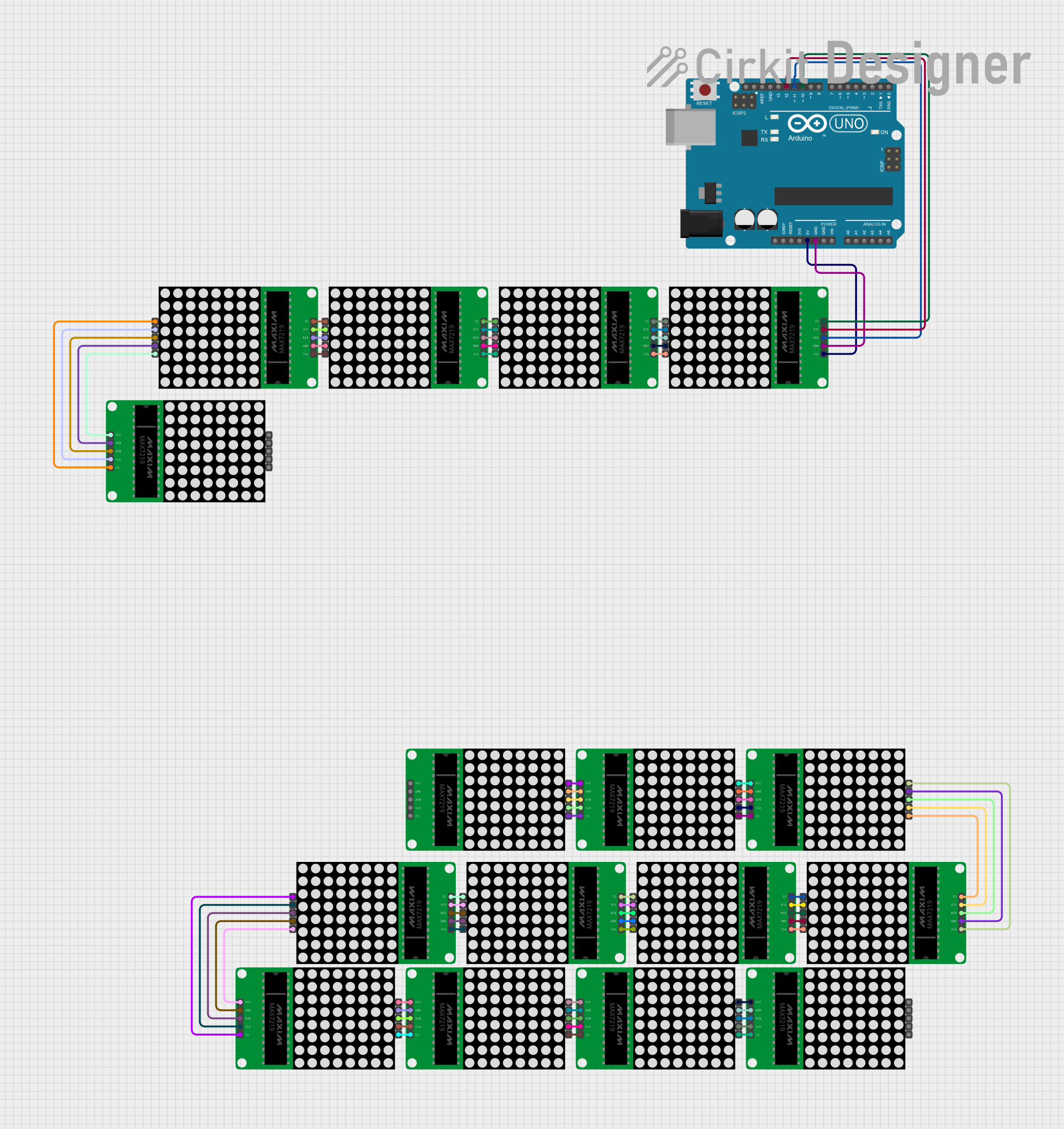
- If multiple MAX7219s are daisy-chained, ensure that the DOUT of the first chip is connected to the DIN of the next.
- Use a logic analyzer or oscilloscope to troubleshoot SPI communication issues.
- Check for solder bridges or cold solder joints that might be causing shorts or open circuits.
FAQs
Q: Can I control individual LEDs with the MAX7219? A: Yes, the MAX7219 can control individual LEDs. You will need to address them as part of the matrix and send the appropriate commands.
Q: How do I adjust the brightness of the display? A: The brightness can be adjusted by sending a command to the intensity register (0x0A) with a value between 0x00 (minimum) and 0x0F (maximum).
Q: Can the MAX7219 be used with microcontrollers other than the Arduino? A: Yes, the MAX7219 can be used with any microcontroller that supports SPI communication. Adjust the pin definitions and SPI setup accordingly.