How to Use ATGM336H: Examples, Pinouts, and Specs
Introduction
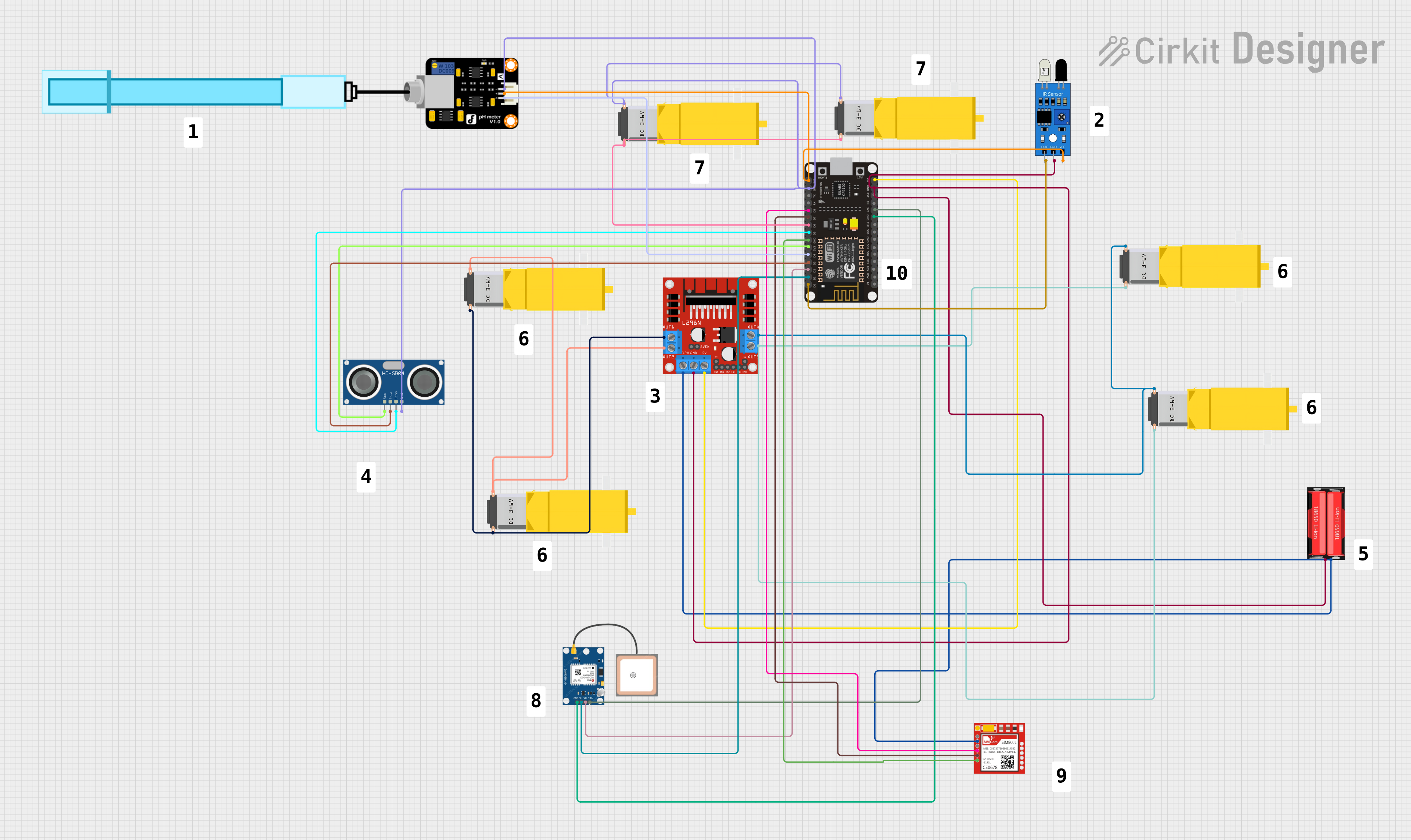
The ATGM336H is a high-performance GPS+BDS dual-mode module manufactured by Teyleten Robot. It is designed to provide accurate positioning data with minimal power consumption. The module features a built-in antenna and supports multiple communication interfaces, making it versatile for a wide range of applications. Its compact design and reliable performance make it ideal for use in robotics, drones, automotive systems, and other GPS-based navigation solutions.
Explore Projects Built with ATGM336H
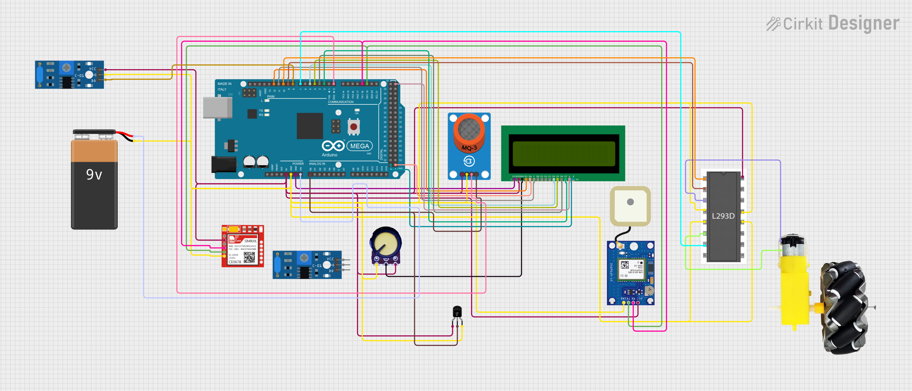
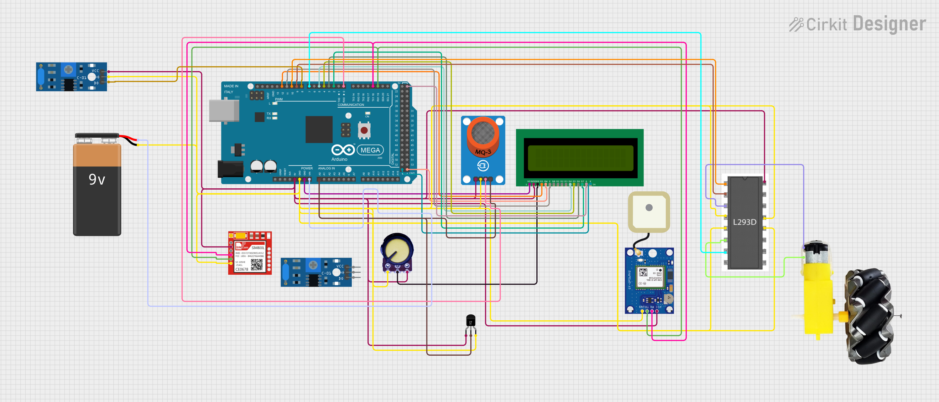
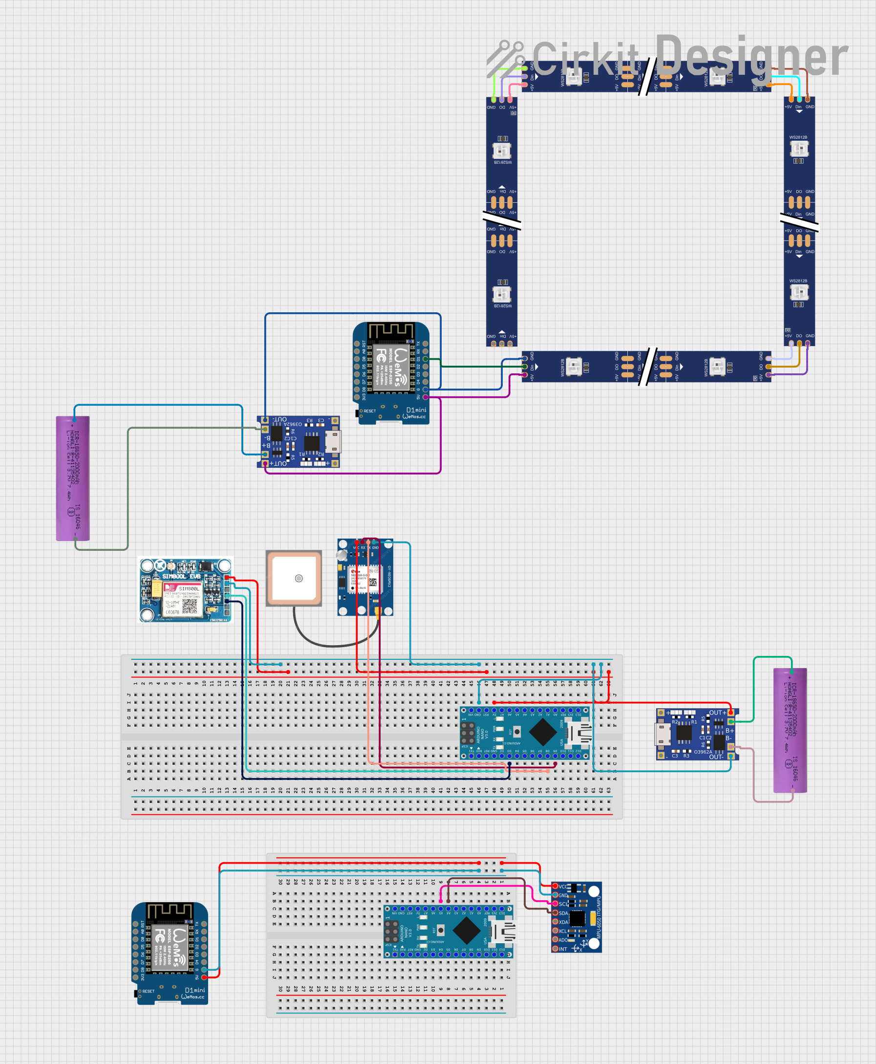
Explore Projects Built with ATGM336H
Common Applications
- Robotics and autonomous systems
- Drones and UAVs
- Automotive navigation and tracking
- IoT devices requiring location services
- Personal navigation devices
Technical Specifications
Key Technical Details
| Parameter | Value |
|---|---|
| Manufacturer | Teyleten Robot |
| Part ID | GPS+BDS Dual-Mode Module |
| Positioning Systems | GPS, BDS (BeiDou Navigation Satellite) |
| Operating Voltage | 3.3V - 5.0V |
| Current Consumption | < 30mA (typical) |
| Communication Interfaces | UART, I2C |
| Baud Rate (Default) | 9600 bps |
| Positioning Accuracy | < 2.5 meters |
| Cold Start Time | < 35 seconds |
| Hot Start Time | < 1 second |
| Operating Temperature | -40°C to +85°C |
| Dimensions | 16mm x 12.2mm x 2.4mm |
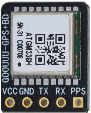
Pin Configuration and Descriptions
| Pin Number | Pin Name | Description |
|---|---|---|
| 1 | VCC | Power supply input (3.3V - 5.0V) |
| 2 | GND | Ground |
| 3 | TXD | UART Transmit Data |
| 4 | RXD | UART Receive Data |
| 5 | PPS | Pulse Per Second output for timing |
| 6 | SDA | I2C Data Line |
| 7 | SCL | I2C Clock Line |
| 8 | NC | Not Connected (leave unconnected) |
Usage Instructions
How to Use the ATGM336H in a Circuit
- Power Supply: Connect the VCC pin to a 3.3V or 5.0V power source and the GND pin to ground.
- Communication Interface:
- For UART communication, connect the TXD and RXD pins to the corresponding RX and TX pins of your microcontroller.
- For I2C communication, connect the SDA and SCL pins to the I2C data and clock lines of your microcontroller.
- Antenna: The module has a built-in antenna, so no external antenna is required for most applications.
- Pulse Per Second (PPS): Use the PPS pin if precise timing signals are needed for your application.
Important Considerations and Best Practices
- Ensure the power supply voltage is within the specified range (3.3V - 5.0V) to avoid damaging the module.
- Place the module in an open area with minimal obstructions for optimal satellite signal reception.
- Use decoupling capacitors near the VCC pin to reduce noise and improve stability.
- If using UART, ensure the baud rate of your microcontroller matches the module's default baud rate (9600 bps) or configure it accordingly.
Example: Connecting the ATGM336H to an Arduino UNO
Below is an example of how to connect and use the ATGM336H module with an Arduino UNO via UART.
Wiring Diagram
| ATGM336H Pin | Arduino UNO Pin |
|---|---|
| VCC | 5V |
| GND | GND |
| TXD | Pin 10 (RX) |
| RXD | Pin 11 (TX) |
Arduino Code
#include <SoftwareSerial.h>

// Define RX and TX pins for SoftwareSerial
SoftwareSerial gpsSerial(10, 11); // RX = Pin 10, TX = Pin 11

void setup() {
  Serial.begin(9600); // Initialize Serial Monitor at 9600 bps
  gpsSerial.begin(9600); // Initialize GPS module at 9600 bps

  Serial.println("ATGM336H GPS Module Test");
}

void loop() {
  // Check if data is available from the GPS module
  while (gpsSerial.available()) {
    char c = gpsSerial.read(); // Read a character from the GPS module
    Serial.print(c); // Print the character to the Serial Monitor
  }
}
Notes
- The
SoftwareSeriallibrary is used to create a secondary serial port for communication with the GPS module. - Ensure the Arduino UNO's Serial Monitor is set to 9600 baud to view the GPS data.
Troubleshooting and FAQs
Common Issues and Solutions
No Data Output from the Module
- Cause: Incorrect wiring or baud rate mismatch.
- Solution: Double-check the connections and ensure the baud rate is set to 9600 bps.
Poor GPS Signal Reception
- Cause: Obstructions or interference in the environment.
- Solution: Place the module in an open area with a clear view of the sky.
Module Not Powering On
- Cause: Insufficient or incorrect power supply.
- Solution: Verify the power supply voltage is within the 3.3V - 5.0V range.
Data Corruption in Output
- Cause: Noise or interference on the communication lines.
- Solution: Use shorter wires and add pull-up resistors for I2C lines if necessary.
FAQs
Q: Can the ATGM336H be used indoors?
A: While the module can operate indoors, GPS signal reception may be weak or unavailable. For best results, use the module in an open area.
Q: How do I change the baud rate of the module?
A: The baud rate can be configured by sending specific commands to the module. Refer to the manufacturer's datasheet for details.
Q: Does the module support external antennas?
A: The ATGM336H has a built-in antenna, but some variants may support external antennas. Check the specific model's datasheet for more information.
Q: What is the purpose of the PPS pin?
A: The PPS (Pulse Per Second) pin provides a precise timing signal that can be used for synchronization in time-sensitive applications.