
How to Use Prototype PCB Solderable Breadboard: Examples, Pinouts, and Specs
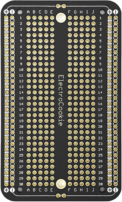
 Design with Prototype PCB Solderable Breadboard in Cirkit Designer
Introduction
The Prototype PCB Solderable Breadboard (Manufacturer: ElectroCookie, Part ID: ECPB_H_BK'_5P) is a versatile platform designed for prototyping and testing electronic circuits. Unlike traditional breadboards, this solderable version allows users to permanently secure components once a design is finalized, while still maintaining the familiar layout of a standard breadboard. This makes it an excellent choice for transitioning from temporary to semi-permanent circuit designs.
Explore Projects Built with Prototype PCB Solderable Breadboard
 Open Project in Cirkit Designer
 Open Project in Cirkit Designer
 Open Project in Cirkit Designer
 Open Project in Cirkit Designer
Explore Projects Built with Prototype PCB Solderable Breadboard
Open Project in Cirkit DesignerOpen Project in Cirkit DesignerOpen Project in Cirkit DesignerOpen Project in Cirkit DesignerCommon Applications and Use Cases
- Prototyping and testing electronic circuits
- Educational projects and learning environments
- Transitioning from breadboard designs to soldered circuits
- Small-scale production of custom circuit boards
- DIY electronics and hobbyist projects
Technical Specifications
The following table outlines the key technical details of the Prototype PCB Solderable Breadboard:
| Parameter | Specification |
|---|---|
| Manufacturer | ElectroCookie |
| Part ID | ECPB_H_BK'_5P |
| Material | High-quality FR4 PCB |
| Dimensions | 83mm x 55mm x 1.6mm |
| Layout | Standard breadboard layout with power rails |
| Hole Pitch | 2.54mm (0.1 inch) |
| Hole Diameter | 1.0mm (suitable for standard through-hole components) |
| Copper Layer | Double-sided with tinned pads |
| Pad Configuration | Solderable pads in breadboard-style rows and columns |
| Power Rails | Dedicated power and ground rails on both sides |
| Compatibility | Compatible with standard DIP ICs and components |
Pin Configuration and Descriptions
The Prototype PCB Solderable Breadboard does not have traditional pins but features a layout similar to a standard breadboard. Below is a description of its key sections:
| Section | Description |
|---|---|
| Power Rails | Two rows on each side for power (VCC) and ground (GND). |
| Terminal Strips | Central area with rows of interconnected pads for components. |
| Solder Pads | Individual pads for soldering components securely. |
| Mounting Holes | Four corner holes for securing the PCB to enclosures. |
Usage Instructions
How to Use the Component in a Circuit
- Plan Your Circuit: Design your circuit layout on paper or using software before transferring it to the solderable breadboard.
- Place Components: Insert components into the holes, ensuring proper alignment with the breadboard layout.
- Solder Connections: Use a soldering iron to secure components to the PCB. Apply solder to the pads to create permanent connections.
- Connect Power Rails: Use jumper wires or solder bridges to connect the power and ground rails to your circuit.
- Test the Circuit: Verify the functionality of your circuit using a multimeter or other testing tools.
Important Considerations and Best Practices
- Avoid Overheating: Excessive heat during soldering can damage the PCB or components. Use a temperature-controlled soldering iron.
- Use Flux: Apply flux to ensure clean and reliable solder joints.
- Plan for Rework: Leave some space between components to allow for modifications or repairs.
- Label Connections: Use a marker or labels to identify power, ground, and signal lines for easier debugging.
- Clean the PCB: After soldering, clean the PCB with isopropyl alcohol to remove flux residue.
Example: Connecting to an Arduino UNO
The Prototype PCB Solderable Breadboard can be used to create custom shields or circuits for an Arduino UNO. Below is an example of connecting an LED and resistor to an Arduino:
// Example: Blinking an LED connected via the solderable breadboard
// Connect the LED's anode (+) to Arduino pin 13 and cathode (-) to GND
// Use a 220-ohm resistor in series with the LED to limit current

void setup() {
  pinMode(13, OUTPUT); // Set pin 13 as an output
}

void loop() {
  digitalWrite(13, HIGH); // Turn the LED on
  delay(1000);            // Wait for 1 second
  digitalWrite(13, LOW);  // Turn the LED off
  delay(1000);            // Wait for 1 second
}
Troubleshooting and FAQs
Common Issues Users Might Face
Cold Solder Joints: Connections may appear soldered but are not electrically conductive.
- Solution: Reheat the joint and apply a small amount of solder to ensure a proper connection.
Short Circuits: Adjacent solder pads may accidentally connect, causing a short circuit.
- Solution: Use a multimeter to check for shorts and remove excess solder with a desoldering pump or wick.
Component Misalignment: Components may not align with the breadboard layout.
- Solution: Double-check the layout before soldering and use a breadboard for initial prototyping.
Damaged Pads: Excessive heat or force can lift pads from the PCB.
- Solution: Use minimal heat and avoid excessive soldering time. If a pad is damaged, use jumper wires to reroute connections.
FAQs
Q: Can I reuse the solderable breadboard after soldering?
A: No, the solderable breadboard is designed for permanent connections. Once soldered, components cannot be easily removed without damaging the PCB.
Q: Is this compatible with surface-mount components?
A: The breadboard is primarily designed for through-hole components. However, with careful soldering, small surface-mount components can be used.
Q: How do I connect multiple power rails?
A: Use solder bridges or jumper wires to connect power rails as needed.
Q: Can I cut the PCB to a smaller size?
A: Yes, the PCB can be cut using a hacksaw or rotary tool, but ensure that the cut does not damage critical connections.
This documentation provides a comprehensive guide to using the ElectroCookie Prototype PCB Solderable Breadboard effectively for your electronic projects.