
How to Use Adafruit CYBERDECK HAT: Examples, Pinouts, and Specs
 Design with Adafruit CYBERDECK HAT in Cirkit Designer
Introduction
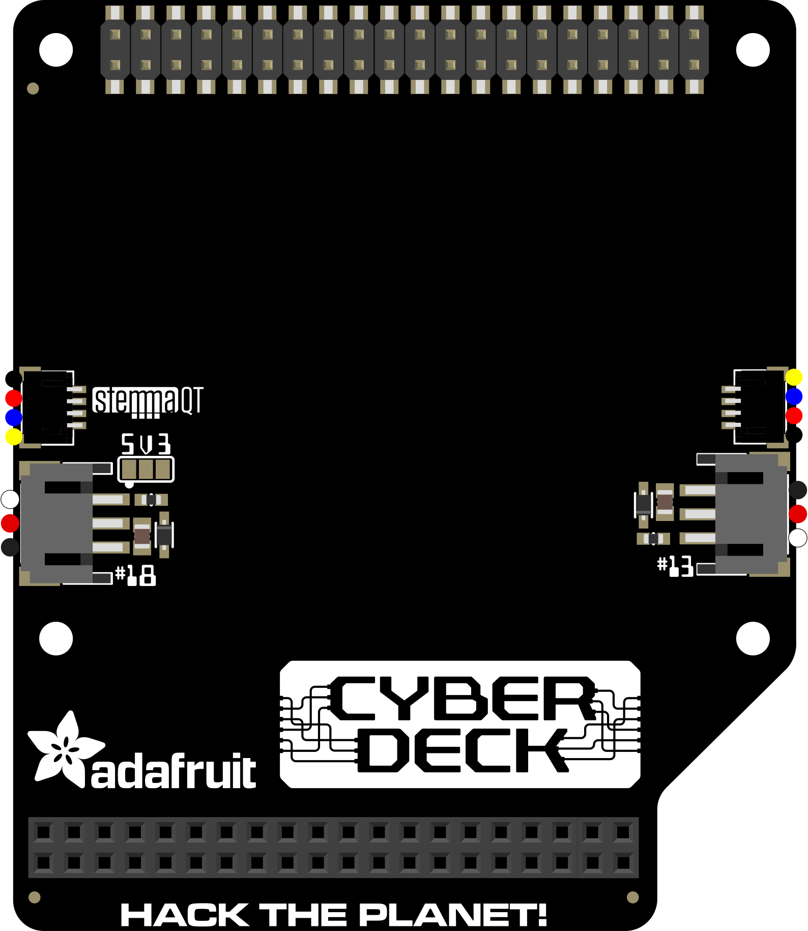
The Adafruit CYBERDECK HAT (Part ID: 4863) is a versatile add-on board designed for Raspberry Pi. It features a variety of interfaces and connectors, making it an excellent choice for enhancing DIY projects. This HAT is particularly well-suited for creating portable computing devices, such as cyberdecks, handheld consoles, or compact workstations. Its design allows for seamless integration with Raspberry Pi boards, providing a robust platform for creative and functional builds.
Explore Projects Built with Adafruit CYBERDECK HAT
 Open Project in Cirkit Designer
 Open Project in Cirkit Designer
 Open Project in Cirkit Designer
 Open Project in Cirkit Designer
Explore Projects Built with Adafruit CYBERDECK HAT
Open Project in Cirkit DesignerOpen Project in Cirkit DesignerOpen Project in Cirkit DesignerOpen Project in Cirkit DesignerCommon Applications and Use Cases
- Building portable computing devices (e.g., cyberdecks)
- Creating handheld gaming consoles
- Prototyping compact Raspberry Pi-based workstations
- Enhancing Raspberry Pi projects with additional connectivity options
- Educational and maker projects requiring modularity and portability
Technical Specifications
The Adafruit CYBERDECK HAT is designed to interface with Raspberry Pi boards and offers a range of features to support various applications.
Key Technical Details
- Manufacturer: Adafruit
- Part ID: 4863
- Compatibility: Raspberry Pi boards with a 40-pin GPIO header
- Dimensions: 65mm x 56mm x 10mm (approx.)
- Weight: ~20g
- Connectors:
- 40-pin GPIO pass-through header
- Additional connectors for modular expansion
- Power Requirements: Powered via Raspberry Pi GPIO header
- Operating Temperature: 0°C to 50°C
Pin Configuration and Descriptions
The Adafruit CYBERDECK HAT uses the standard 40-pin GPIO header of the Raspberry Pi. Below is the pinout description:
| Pin | Name | Description |
|---|---|---|
| 1 | 3.3V | Power supply (3.3V) |
| 2 | 5V | Power supply (5V) |
| 3 | GPIO2 (SDA1) | I2C Data Line |
| 4 | 5V | Power supply (5V) |
| 5 | GPIO3 (SCL1) | I2C Clock Line |
| 6 | GND | Ground |
| 7 | GPIO4 | General Purpose I/O |
| 8 | GPIO14 (TXD) | UART Transmit |
| 9 | GND | Ground |
| 10 | GPIO15 (RXD) | UART Receive |
| ... | ... | ... (Standard Raspberry Pi GPIO pinout) |
For a complete GPIO pinout, refer to the Raspberry Pi documentation.
Usage Instructions
The Adafruit CYBERDECK HAT is straightforward to use and integrates seamlessly with Raspberry Pi boards. Follow the steps below to get started:
How to Use the Component in a Circuit
- Attach the HAT: Align the 40-pin GPIO header on the CYBERDECK HAT with the GPIO pins on your Raspberry Pi. Gently press down to secure the connection.
- Power the Raspberry Pi: The HAT draws power directly from the Raspberry Pi, so no additional power source is required.
- Connect Peripherals: Use the additional connectors on the HAT to attach peripherals such as displays, keyboards, or other modules.
- Program Your Raspberry Pi: Write and upload code to your Raspberry Pi to interact with the peripherals connected via the CYBERDECK HAT.
Important Considerations and Best Practices
- GPIO Compatibility: Ensure that the peripherals you connect are compatible with the Raspberry Pi GPIO pinout.
- Power Management: Avoid overloading the GPIO pins with high-current devices. Use external power supplies for power-hungry peripherals.
- Static Precautions: Handle the HAT and Raspberry Pi with care to avoid damage from static electricity.
- Software Configuration: Depending on your project, you may need to enable specific interfaces (e.g., I2C, UART) in the Raspberry Pi configuration.
Example Code for Raspberry Pi
Below is an example Python script to enable I2C communication with a peripheral connected via the CYBERDECK HAT:
Import necessary libraries
import smbus import time
Initialize the I2C bus
On Raspberry Pi, I2C bus 1 is typically used
bus = smbus.SMBus(1)
Define the I2C address of the peripheral
DEVICE_ADDRESS = 0x20 # Replace with your device's I2C address
Define a register and data to write
REGISTER = 0x01 # Replace with the target register DATA = 0xFF # Replace with the data to write
try: # Write data to the register bus.write_byte_data(DEVICE_ADDRESS, REGISTER, DATA) print("Data written successfully!")
# Read data from the register
read_data = bus.read_byte_data(DEVICE_ADDRESS, REGISTER)
print(f"Data read from device: {read_data}")
except Exception as e: print(f"Error: {e}")
Close the I2C bus
bus.close()
> **Note**: Ensure that the I2C interface is enabled on your Raspberry Pi. You can enable it using the `raspi-config` tool.
Troubleshooting and FAQs
Common Issues Users Might Face
HAT Not Detected by Raspberry Pi:
- Ensure the HAT is properly seated on the GPIO header.
- Verify that the Raspberry Pi is powered on and functioning correctly.
- Check if the required interfaces (e.g., I2C, UART) are enabled in the Raspberry Pi configuration.
Peripheral Devices Not Working:
- Confirm that the connected peripherals are compatible with the Raspberry Pi GPIO pinout.
- Double-check the wiring and connections.
- Verify the software configuration and ensure the correct drivers are installed.
Overheating or Power Issues:
- Avoid connecting high-power peripherals directly to the GPIO pins.
- Use an external power supply for power-hungry devices.
Solutions and Tips for Troubleshooting
- Use a multimeter to check the voltage levels on the GPIO pins.
- Test the HAT with a different Raspberry Pi board to rule out hardware issues.
- Refer to the Adafruit CYBERDECK HAT product page and Raspberry Pi documentation for additional support.
By following this documentation, you can effectively integrate the Adafruit CYBERDECK HAT into your Raspberry Pi projects and troubleshoot common issues with ease.