How to Use PING_Schematic: Examples, Pinouts, and Specs
Introduction
The PING schematic is a diagram that represents the connections and layout of a PING sensor circuit. The PING sensor is an ultrasonic distance measurement device that emits ultrasonic waves and calculates the time taken for the echo to return, allowing for precise distance measurements. This schematic is essential for understanding how to integrate the PING sensor into a circuit and ensure proper functionality.
Explore Projects Built with PING_Schematic
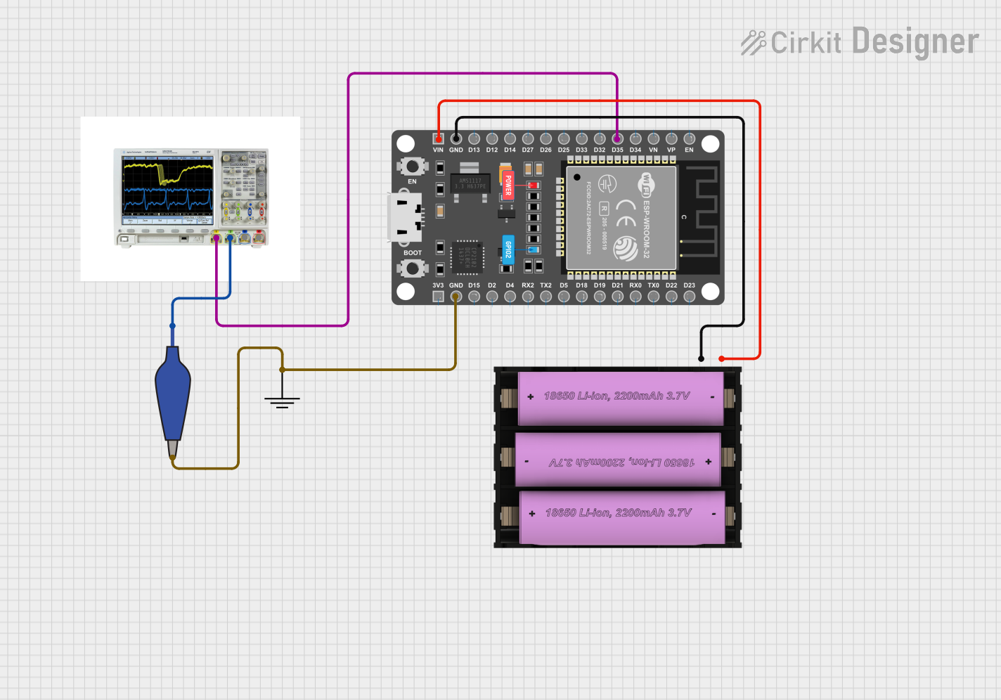


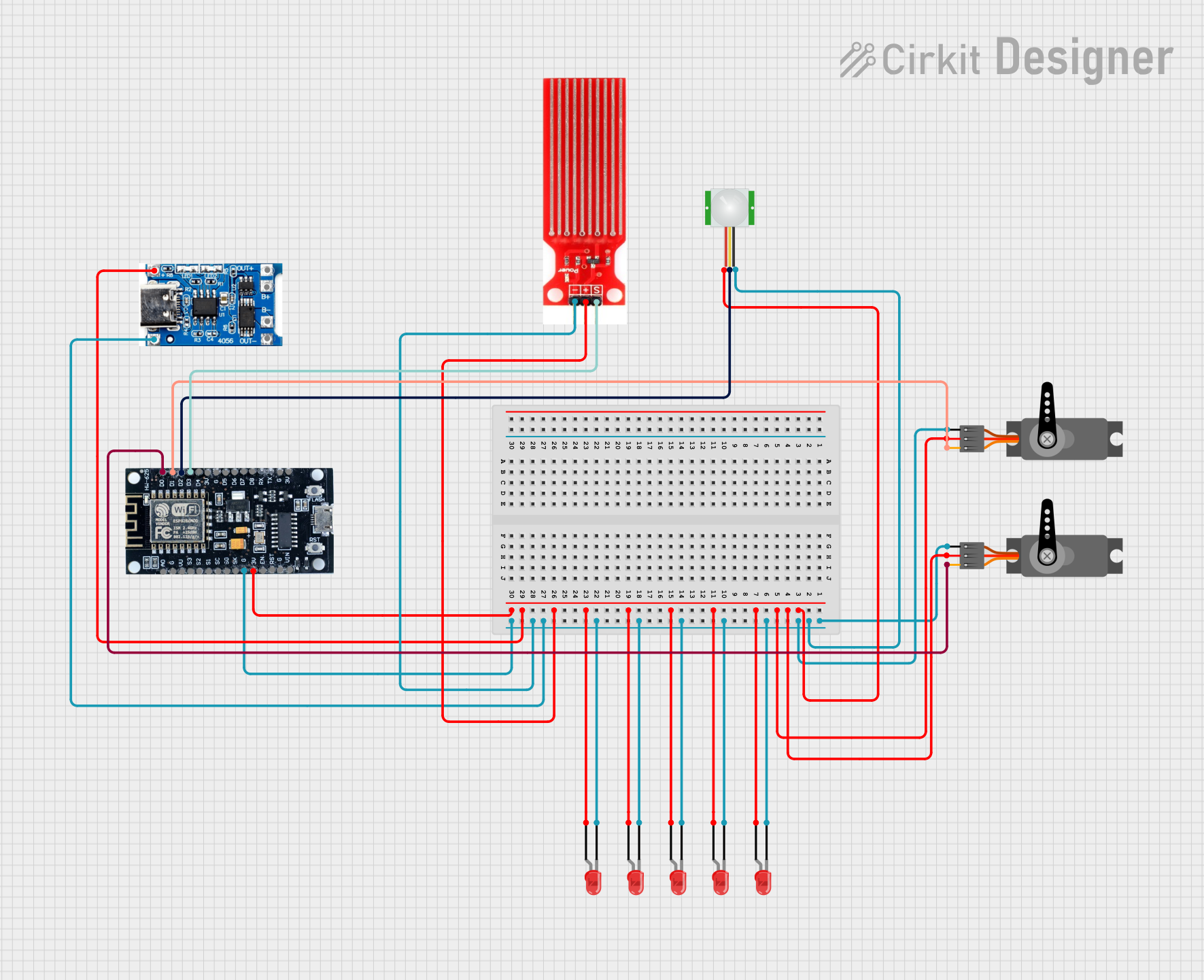
Explore Projects Built with PING_Schematic
Common Applications and Use Cases
- Obstacle detection in robotics
- Distance measurement in automation systems
- Proximity sensing in security systems
- Object tracking in smart devices
- Educational projects involving Arduino or other microcontrollers
Technical Specifications
The PING sensor operates using ultrasonic waves and requires proper connections as outlined in the schematic. Below are the key technical details and pin configuration:
Key Technical Details
- Operating Voltage: 5V DC
- Operating Current: 20 mA (typical)
- Measurement Range: 2 cm to 3 m
- Frequency: 40 kHz (ultrasonic pulse)
- Output Signal: Pulse width proportional to distance
- Trigger Input Signal: 5V TTL, minimum 2 µs pulse
- Echo Output Signal: 5V TTL, pulse width proportional to distance
Pin Configuration and Descriptions
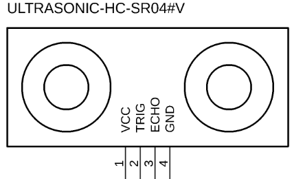
The PING sensor typically has three pins, as shown in the table below:
| Pin | Name | Description |
|---|---|---|
| 1 | VCC | Connects to the 5V power supply of the circuit. |
| 2 | TRIG/ECHO | Acts as both the trigger input and echo output pin. Sends and receives signals. |
| 3 | GND | Connects to the ground of the circuit. |
Usage Instructions
To use the PING sensor in a circuit, follow these steps:
Power the Sensor:
- Connect the VCC pin to a 5V power source.
- Connect the GND pin to the ground of the circuit.
Connect the TRIG/ECHO Pin:
- The TRIG/ECHO pin serves a dual purpose. It is used to send a trigger signal and receive the echo signal.
- Connect this pin to a digital I/O pin on your microcontroller (e.g., Arduino UNO).
Trigger the Sensor:
- Send a 5V TTL pulse of at least 2 µs to the TRIG/ECHO pin to initiate a measurement.
Read the Echo Signal:
- Measure the duration of the pulse on the TRIG/ECHO pin. The pulse width is proportional to the distance of the object.
Calculate the Distance:
- Use the formula:
[ \text{Distance (cm)} = \frac{\text{Pulse Duration (µs)}}{58} ]
- Use the formula:
Example Arduino Code
Below is an example of how to use the PING sensor with an Arduino UNO:
// Define the pin connected to the TRIG/ECHO pin of the PING sensor
const int pingPin = 7;

void setup() {
  // Initialize serial communication for debugging
  Serial.begin(9600);

  // Set the pingPin as an output for triggering and input for echo
  pinMode(pingPin, OUTPUT);
}

void loop() {
  // Send a 10 µs pulse to trigger the sensor
  digitalWrite(pingPin, LOW);
  delayMicroseconds(2);
  digitalWrite(pingPin, HIGH);
  delayMicroseconds(10);
  digitalWrite(pingPin, LOW);

  // Set the pin to input mode to read the echo
  pinMode(pingPin, INPUT);
  long duration = pulseIn(pingPin, HIGH);

  // Calculate the distance in cm
  long distance = duration / 58;

  // Print the distance to the Serial Monitor
  Serial.print("Distance: ");
  Serial.print(distance);
  Serial.println(" cm");

  // Wait before the next measurement
  delay(100);
}
Important Considerations and Best Practices
- Ensure the sensor is powered with a stable 5V supply to avoid inaccurate readings.
- Avoid placing the sensor near objects that can cause interference, such as vibrating surfaces or reflective materials.
- Use a decoupling capacitor (e.g., 10 µF) between VCC and GND to reduce noise.
- If using multiple PING sensors, ensure they are triggered sequentially to prevent cross-interference.
Troubleshooting and FAQs
Common Issues and Solutions
No Output Signal:
- Ensure the sensor is properly powered (5V to VCC and GND connected).
- Verify the trigger pulse is at least 2 µs long.
Inaccurate Distance Measurements:
- Check for obstacles or reflective surfaces near the sensor that may cause false readings.
- Ensure the sensor is mounted securely to avoid vibrations.
Interference Between Multiple Sensors:
- Trigger sensors one at a time with a delay between measurements to prevent cross-talk.
Sensor Not Responding:
- Verify the connections and ensure the TRIG/ECHO pin is correctly connected to the microcontroller.
FAQs
Q: Can the PING sensor measure distances below 2 cm?
A: No, the minimum measurement range of the PING sensor is 2 cm. Objects closer than this may not be detected accurately.
Q: Can I use the PING sensor with a 3.3V microcontroller?
A: The PING sensor requires a 5V power supply. However, you can use a level shifter to interface the TRIG/ECHO pin with a 3.3V microcontroller.
Q: How do I reduce noise in the sensor readings?
A: Use a decoupling capacitor between VCC and GND, and ensure the sensor is placed away from sources of electrical noise.
By following this documentation, you can effectively integrate and troubleshoot the PING sensor in your projects.