
How to Use MCP4921: Examples, Pinouts, and Specs
 Design with MCP4921 in Cirkit Designer
Introduction
The MCP4921 is a 12-bit digital-to-analog converter (DAC) manufactured by Microchip Technology. It is designed to convert digital signals into precise analog voltages, making it an essential component in applications requiring digital-to-analog conversion. The MCP4921 features a single-channel output, an SPI (Serial Peripheral Interface) communication interface, and an internal voltage reference. Its compact design and high resolution make it ideal for applications such as audio signal processing, waveform generation, motor control, and industrial automation.
Explore Projects Built with MCP4921
 Open Project in Cirkit Designer
 Open Project in Cirkit Designer
 Open Project in Cirkit Designer
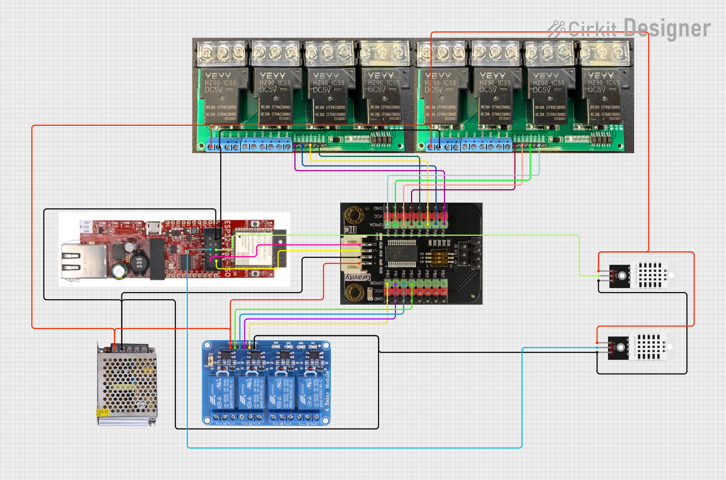 Open Project in Cirkit Designer
Explore Projects Built with MCP4921
Open Project in Cirkit DesignerOpen Project in Cirkit DesignerOpen Project in Cirkit DesignerOpen Project in Cirkit DesignerCommon Applications
- Audio signal processing
- Waveform generation
- Motor speed and position control
- Industrial process control
- Data acquisition systems
- Analog output for microcontroller-based systems
Technical Specifications
The MCP4921 is a high-performance DAC with the following key specifications:
| Parameter | Value |
|---|---|
| Resolution | 12-bit |
| Output Channels | 1 |
| Interface | SPI |
| Supply Voltage (VDD) | 2.7V to 5.5V |
| Output Voltage Range | 0V to VREF (configurable) |
| Maximum Output Current | 25 mA |
| Settling Time | 4.5 µs (typical) |
| SPI Clock Frequency | Up to 20 MHz |
| Operating Temperature Range | -40°C to +125°C |
| Package Options | 8-pin PDIP, SOIC, MSOP |
Pin Configuration and Descriptions
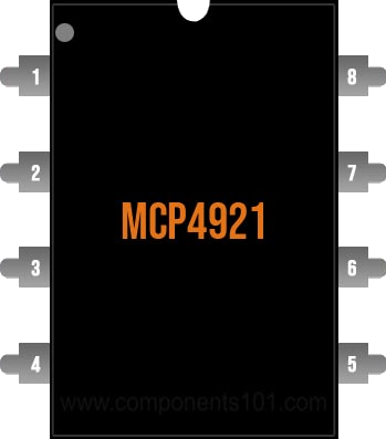
The MCP4921 is an 8-pin device. The pinout and descriptions are as follows:
| Pin Number | Pin Name | Description |
|---|---|---|
| 1 | VDD | Positive power supply (2.7V to 5.5V). |
| 2 | CS | Chip Select (active low). Enables SPI communication when pulled low. |
| 3 | SCK | Serial Clock Input. Used to synchronize data transfer over SPI. |
| 4 | SDI | Serial Data Input. Receives data from the microcontroller via SPI. |
| 5 | LDAC | Latch DAC Input (active low). Updates the DAC output when pulled low. |
| 6 | VOUT | Analog output voltage. |
| 7 | VREF | Voltage reference input. Determines the maximum output voltage range. |
| 8 | GND | Ground connection. |
Usage Instructions
How to Use the MCP4921 in a Circuit
- Power Supply: Connect the VDD pin to a stable power supply (2.7V to 5.5V) and the GND pin to ground.
- Voltage Reference: Provide a reference voltage to the VREF pin. This voltage determines the maximum output voltage range of the DAC.
- SPI Communication:
- Connect the CS, SCK, and SDI pins to the corresponding SPI pins on your microcontroller.
- Ensure the SPI clock frequency does not exceed 20 MHz.
- Output Connection: Connect the VOUT pin to the desired load or circuit where the analog signal is required.
- LDAC Pin: Tie the LDAC pin to ground if you want the DAC output to update automatically after each SPI transaction. Alternatively, control it via the microcontroller for manual updates.
Important Considerations
- Use decoupling capacitors (e.g., 0.1 µF) between VDD and GND to reduce noise and ensure stable operation.
- Ensure the reference voltage (VREF) is stable and within the specified range for accurate output.
- Avoid exceeding the maximum output current (25 mA) to prevent damage to the device.
- Use proper SPI settings: CPOL = 0, CPHA = 0 (SPI Mode 0).
Example Code for Arduino UNO
Below is an example of how to interface the MCP4921 with an Arduino UNO using SPI:
#include <SPI.h>

// Define MCP4921 pins
const int CS_PIN = 10; // Chip Select pin connected to Arduino pin 10

void setup() {
  // Initialize SPI communication
  SPI.begin();
  SPI.setClockDivider(SPI_CLOCK_DIV2); // Set SPI clock speed (16 MHz / 2 = 8 MHz)
  SPI.setDataMode(SPI_MODE0);          // SPI Mode 0: CPOL = 0, CPHA = 0
  SPI.setBitOrder(MSBFIRST);           // Send most significant bit first

  // Configure Chip Select pin
  pinMode(CS_PIN, OUTPUT);
  digitalWrite(CS_PIN, HIGH); // Set CS pin high (inactive)
}

void loop() {
  uint16_t value = 2048; // Example 12-bit value (midpoint of 0-4095 range)

  // Send data to MCP4921
  digitalWrite(CS_PIN, LOW); // Activate the MCP4921
  SPI.transfer(0x30 | (value >> 8)); // Send upper 4 bits with configuration bits
  SPI.transfer(value & 0xFF);        // Send lower 8 bits
  digitalWrite(CS_PIN, HIGH); // Deactivate the MCP4921

  delay(1000); // Wait 1 second before sending the next value
}
Explanation of the Code
- The
SPI.transfer()function sends data to the MCP4921 over the SPI bus. - The first byte contains configuration bits (e.g., DAC channel selection) and the upper 4 bits of the 12-bit value.
- The second byte contains the lower 8 bits of the 12-bit value.
- The
CS_PINis toggled to enable and disable communication with the MCP4921.
Troubleshooting and FAQs
Common Issues and Solutions
No Output Voltage:
- Ensure the VDD and GND pins are properly connected.
- Verify that the SPI communication settings (clock speed, mode, etc.) are correct.
- Check that the CS pin is being toggled correctly during SPI transactions.
Incorrect Output Voltage:
- Verify the reference voltage (VREF) is stable and within the specified range.
- Ensure the 12-bit digital value being sent to the MCP4921 is correct.
- Check for noise or interference on the SPI lines.
Output Voltage is Noisy:
- Add decoupling capacitors near the VDD and VREF pins.
- Use shielded cables or shorter connections for SPI lines to reduce noise.
SPI Communication Fails:
- Double-check the wiring between the microcontroller and the MCP4921.
- Ensure the SPI clock frequency does not exceed 20 MHz.
- Verify that the microcontroller's SPI pins are correctly configured.
FAQs
Q: Can I use the MCP4921 with a 3.3V microcontroller?
A: Yes, the MCP4921 operates with a supply voltage range of 2.7V to 5.5V, making it compatible with 3.3V systems.
Q: What happens if I leave the LDAC pin floating?
A: The LDAC pin should not be left floating. Tie it to ground for automatic updates or control it via the microcontroller for manual updates.
Q: Can I use the MCP4921 for audio applications?
A: Yes, the MCP4921's 12-bit resolution and fast settling time make it suitable for audio signal generation and processing.
Q: How do I calculate the output voltage?
A: The output voltage is calculated as:
[
V_{OUT} = \left(\frac{D}{4096}\right) \times V_{REF}
]
where (D) is the 12-bit digital value (0 to 4095) and (V_{REF}) is the reference voltage.
By following this documentation, you can effectively integrate the MCP4921 into your projects and achieve precise digital-to-analog conversion.