
How to Use Adafruit LSM6DS3TR-C: Examples, Pinouts, and Specs
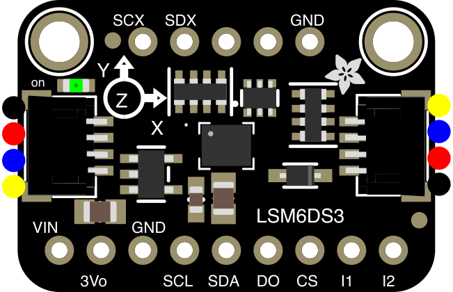
 Design with Adafruit LSM6DS3TR-C in Cirkit Designer
Introduction
The Adafruit LSM6DS3TR-C (Part ID: 4503) is a high-performance 6-DoF (Degrees of Freedom) inertial sensor that integrates a 3-axis accelerometer and a 3-axis gyroscope. This compact sensor is designed for precise motion tracking and orientation detection, making it ideal for applications such as robotics, wearables, gaming devices, and IoT systems. Its low power consumption and high accuracy make it a versatile choice for projects requiring motion sensing.
Explore Projects Built with Adafruit LSM6DS3TR-C
 Open Project in Cirkit Designer
 Open Project in Cirkit Designer
 Open Project in Cirkit Designer
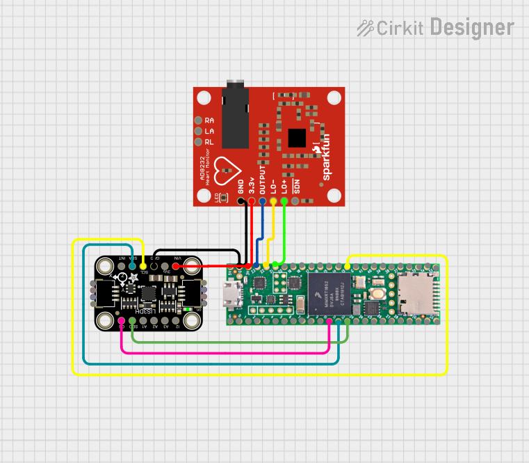 Open Project in Cirkit Designer
Explore Projects Built with Adafruit LSM6DS3TR-C
Open Project in Cirkit DesignerOpen Project in Cirkit DesignerOpen Project in Cirkit DesignerOpen Project in Cirkit DesignerCommon Applications
- Robotics for motion and orientation tracking
- Wearable devices for fitness and health monitoring
- IoT devices for gesture recognition and environmental interaction
- Gaming controllers for motion-based input
- Drones for stabilization and navigation
Technical Specifications
The Adafruit LSM6DS3TR-C offers a range of features and specifications that make it suitable for a variety of applications. Below are the key technical details:
General Specifications
| Parameter | Value |
|---|---|
| Manufacturer | Adafruit |
| Part ID | 4503 |
| Sensor Type | 6-DoF (3-axis accelerometer + 3-axis gyroscope) |
| Communication Interface | I2C, SPI |
| Operating Voltage | 1.71V to 3.6V |
| Operating Temperature | -40°C to +85°C |
| Power Consumption | Ultra-low power mode available |
| Accelerometer Range | ±2g, ±4g, ±8g, ±16g |
| Gyroscope Range | ±125°/s, ±250°/s, ±500°/s, ±1000°/s, ±2000°/s |
| Output Data Rate (ODR) | Up to 6.66 kHz |
| Package Size | 2.5mm x 3mm x 0.83mm |
Pin Configuration
The LSM6DS3TR-C breakout board from Adafruit includes the following pins:
| Pin Name | Description |
|---|---|
| VIN | Power input (3.3V or 5V) |
| GND | Ground |
| SCL | I2C clock line (or SPI clock in SPI mode) |
| SDA | I2C data line (or SPI data in SPI mode) |
| CS | Chip select for SPI (leave unconnected for I2C) |
| INT1 | Interrupt 1 output |
| INT2 | Interrupt 2 output |
Usage Instructions
The Adafruit LSM6DS3TR-C can be easily integrated into your project using I2C or SPI communication. Below are the steps to use the sensor in a circuit and some best practices.
Connecting the Sensor
- Power the Sensor: Connect the
VINpin to a 3.3V or 5V power source and theGNDpin to ground. - I2C Communication:
- Connect the
SCLpin to the I2C clock line on your microcontroller. - Connect the
SDApin to the I2C data line on your microcontroller. - Leave the
CSpin unconnected.
- Connect the
- SPI Communication (optional):
- Connect the
CSpin to a GPIO pin on your microcontroller for chip select. - Use the
SCLandSDApins for SPI clock and data, respectively.
- Connect the
- Interrupts (optional): Connect
INT1and/orINT2to GPIO pins on your microcontroller if you need to use interrupts.
Arduino Example Code
Below is an example of how to use the Adafruit LSM6DS3TR-C with an Arduino UNO via I2C. This example uses the Adafruit LSM6DS library, which can be installed via the Arduino Library Manager.
#include <Wire.h>
#include <Adafruit_LSM6DS3TRC.h>

// Create an instance of the LSM6DS3TR-C sensor
Adafruit_LSM6DS3TRC lsm6ds;

// Setup function to initialize the sensor
void setup() {
  Serial.begin(115200); // Start serial communication at 115200 baud
  while (!Serial) delay(10); // Wait for Serial Monitor to open

  Serial.println("Adafruit LSM6DS3TR-C Test");

  // Initialize the sensor
  if (!lsm6ds.begin_I2C()) {
    Serial.println("Failed to find LSM6DS3TR-C chip");
    while (1) delay(10); // Halt if sensor is not found
  }
  Serial.println("LSM6DS3TR-C Found!");

  // Configure the accelerometer and gyroscope ranges
  lsm6ds.setAccelRange(LSM6DS_ACCEL_RANGE_4_G); // Set accelerometer range to ±4g
  lsm6ds.setGyroRange(LSM6DS_GYRO_RANGE_250_DPS); // Set gyroscope range to ±250°/s
}

// Loop function to read and display sensor data
void loop() {
  sensors_event_t accel, gyro, temp;

  // Get sensor events
  lsm6ds.getEvent(&accel, &gyro, &temp);

  // Print accelerometer data
  Serial.print("Accel X: "); Serial.print(accel.acceleration.x); Serial.print(" m/s^2 ");
  Serial.print("Y: "); Serial.print(accel.acceleration.y); Serial.print(" m/s^2 ");
  Serial.print("Z: "); Serial.print(accel.acceleration.z); Serial.println(" m/s^2");

  // Print gyroscope data
  Serial.print("Gyro X: "); Serial.print(gyro.gyro.x); Serial.print(" rad/s ");
  Serial.print("Y: "); Serial.print(gyro.gyro.y); Serial.print(" rad/s ");
  Serial.print("Z: "); Serial.print(gyro.gyro.z); Serial.println(" rad/s");

  // Print temperature data
  Serial.print("Temperature: "); Serial.print(temp.temperature); Serial.println(" °C");

  delay(500); // Wait 500ms before the next reading
}
Best Practices
- Use appropriate pull-up resistors (typically 4.7kΩ) on the I2C lines if they are not already included on the breakout board.
- Ensure the operating voltage of your microcontroller matches the sensor's voltage requirements.
- Avoid placing the sensor near sources of vibration or electromagnetic interference for accurate readings.
Troubleshooting and FAQs
Common Issues
Sensor Not Detected:
- Ensure the I2C address (default:
0x6A) matches the one in your code. - Check all connections for proper wiring.
- Verify that the sensor is powered correctly.
- Ensure the I2C address (default:
Incorrect or No Data:
- Confirm that the accelerometer and gyroscope ranges are configured correctly.
- Ensure the sensor is not exposed to excessive noise or vibrations.
Interrupts Not Working:
- Verify that the interrupt pins (
INT1andINT2) are connected to the correct GPIO pins. - Check the interrupt configuration in your code.
- Verify that the interrupt pins (
FAQs
Q: Can I use the LSM6DS3TR-C with a 5V microcontroller?
A: Yes, the breakout board includes a voltage regulator and level shifters, allowing it to work with both 3.3V and 5V systems.
Q: How do I switch between I2C and SPI modes?
A: By default, the sensor operates in I2C mode. To use SPI, connect the CS pin to a GPIO pin and configure it in your code.
Q: What is the maximum sampling rate of the sensor?
A: The sensor supports an output data rate (ODR) of up to 6.66 kHz for both the accelerometer and gyroscope.
Q: Can I use this sensor for gesture recognition?
A: Yes, the LSM6DS3TR-C is well-suited for gesture recognition applications due to its high sensitivity and accuracy.
For additional support, refer to the Adafruit LSM6DS3TR-C product page.