
How to Use LED: Two Pin (green) - Long Pins: Examples, Pinouts, and Specs
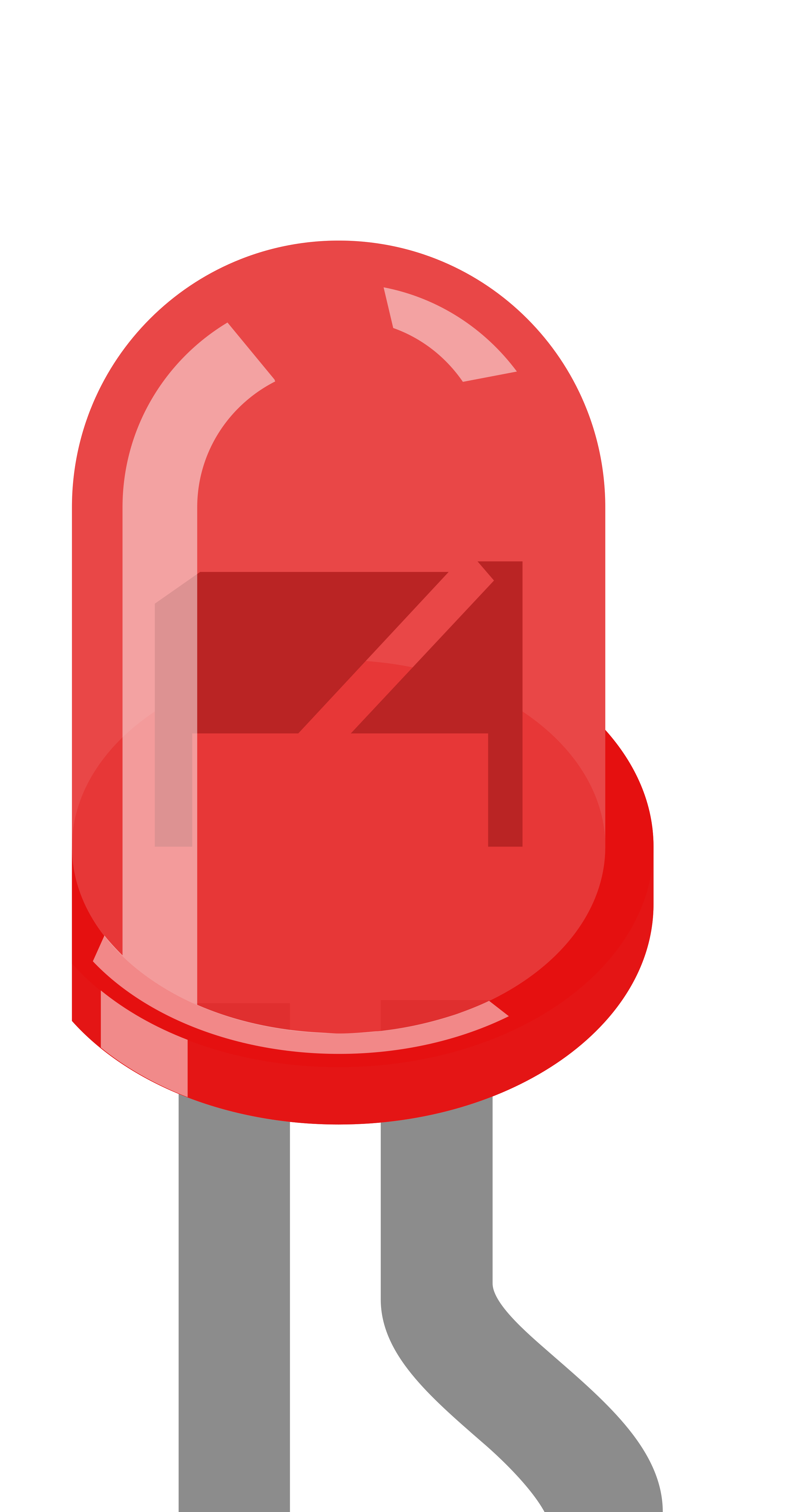
 Design with LED: Two Pin (green) - Long Pins in Cirkit Designer
Introduction
The LED: Two Pin (Green) - Long Pins is a light-emitting diode designed to emit green light when powered. It features two long pins, making it easy to connect in breadboards, PCBs, or other electronic circuits. This component is widely used in visual indicators, status displays, and decorative lighting applications due to its simplicity, efficiency, and reliability.
Explore Projects Built with LED: Two Pin (green) - Long Pins
 Open Project in Cirkit Designer
 Open Project in Cirkit Designer
 Open Project in Cirkit Designer
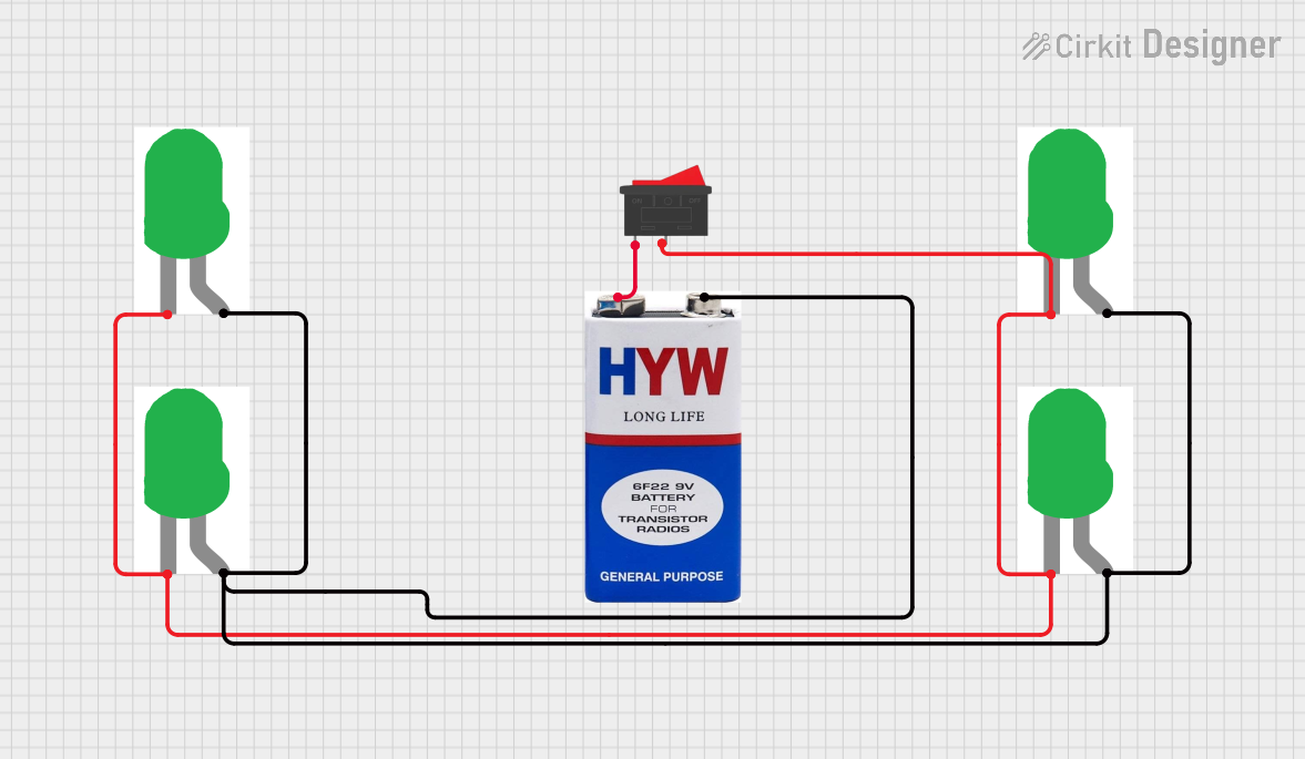 Open Project in Cirkit Designer
Explore Projects Built with LED: Two Pin (green) - Long Pins
Open Project in Cirkit DesignerOpen Project in Cirkit DesignerOpen Project in Cirkit DesignerOpen Project in Cirkit DesignerCommon Applications
- Power and status indicators in electronic devices
- Signal and warning lights
- DIY electronics and hobby projects
- Decorative and ambient lighting
- Educational purposes for learning basic electronics
Technical Specifications
Below are the key technical details for the LED: Two Pin (Green) - Long Pins:
| Parameter | Value |
|---|---|
| Forward Voltage (Vf) | 2.0V - 2.4V |
| Forward Current (If) | 20mA (typical) |
| Maximum Current (Imax) | 30mA |
| Wavelength | 520nm - 530nm (green light) |
| Viewing Angle | 20° - 30° |
| Operating Temperature | -40°C to +85°C |
| Pin Length | 25mm (approx.) |
Pin Configuration
The LED has two pins, each with a specific function:
| Pin | Description |
|---|---|
| Anode (+) | The longer pin, connected to the positive terminal of the power supply or circuit. |
| Cathode (-) | The shorter pin, connected to the negative terminal or ground (GND). |
Usage Instructions
How to Use the LED in a Circuit
Identify the Pins: Locate the longer pin (Anode) and shorter pin (Cathode). The Anode connects to the positive voltage, and the Cathode connects to ground.
Use a Current-Limiting Resistor: To prevent damage, always use a resistor in series with the LED. Calculate the resistor value using Ohm's Law: [ R = \frac{V_{supply} - V_f}{I_f} ]
- (V_{supply}): Supply voltage
- (V_f): Forward voltage of the LED (2.2V typical)
- (I_f): Desired forward current (e.g., 20mA)
For example, with a 5V supply: [ R = \frac{5V - 2.2V}{0.02A} = 140\Omega ] Use the nearest standard resistor value (e.g., 150Ω).
Connect the LED:
- Connect the Anode to the positive terminal of the power supply through the resistor.
- Connect the Cathode to the ground.
Power the Circuit: Apply the appropriate voltage to the circuit. The LED will emit green light.
Example: Connecting to an Arduino UNO
The LED can be easily connected to an Arduino UNO for control. Below is an example of blinking the LED:
Circuit Setup
- Connect the Anode (+) of the LED to Arduino digital pin 13 through a 220Ω resistor.
- Connect the Cathode (-) of the LED to the Arduino GND pin.
Arduino Code
// LED Blink Example for Arduino UNO
// This code blinks an LED connected to pin 13 at 1-second intervals.

const int ledPin = 13; // Define the pin connected to the LED

void setup() {
  pinMode(ledPin, OUTPUT); // Set the LED pin as an output
}

void loop() {
  digitalWrite(ledPin, HIGH); // Turn the LED on
  delay(1000);               // Wait for 1 second
  digitalWrite(ledPin, LOW);  // Turn the LED off
  delay(1000);               // Wait for 1 second
}
Important Considerations
- Polarity: LEDs are polarized components. Reversing the polarity may damage the LED.
- Current Limiting: Always use a resistor to limit the current through the LED.
- Brightness Control: Use Pulse Width Modulation (PWM) to adjust the brightness of the LED.
Troubleshooting and FAQs
Common Issues
LED Does Not Light Up:
Cause: Incorrect polarity.
Solution: Ensure the Anode is connected to the positive voltage and the Cathode to ground.
Cause: No current-limiting resistor or incorrect resistor value.
Solution: Verify the resistor value and connections.
LED is Dim:
- Cause: Insufficient current.
- Solution: Check the resistor value and ensure the supply voltage is adequate.
LED Burned Out:
- Cause: Excessive current.
- Solution: Use a proper current-limiting resistor to prevent overcurrent.
Flickering LED:
- Cause: Unstable power supply or loose connections.
- Solution: Check the power source and ensure all connections are secure.
FAQs
Q: Can I connect the LED directly to a 3.3V or 5V power supply?
A: No, you must use a current-limiting resistor to prevent excessive current, which can damage the LED.
Q: How do I calculate the resistor value for different supply voltages?
A: Use the formula (R = \frac{V_{supply} - V_f}{I_f}), where (V_f) is the forward voltage (2.2V typical) and (I_f) is the desired current (e.g., 20mA).
Q: Can I use this LED with a PWM signal?
A: Yes, the LED can be dimmed or controlled using a PWM signal from a microcontroller like Arduino.
Q: What happens if I reverse the polarity?
A: The LED will not light up, and prolonged reverse polarity may damage the component.
By following this documentation, you can effectively use the LED: Two Pin (Green) - Long Pins in your electronic projects.