
How to Use L9110S DC motor driver for 4 motors: Examples, Pinouts, and Specs
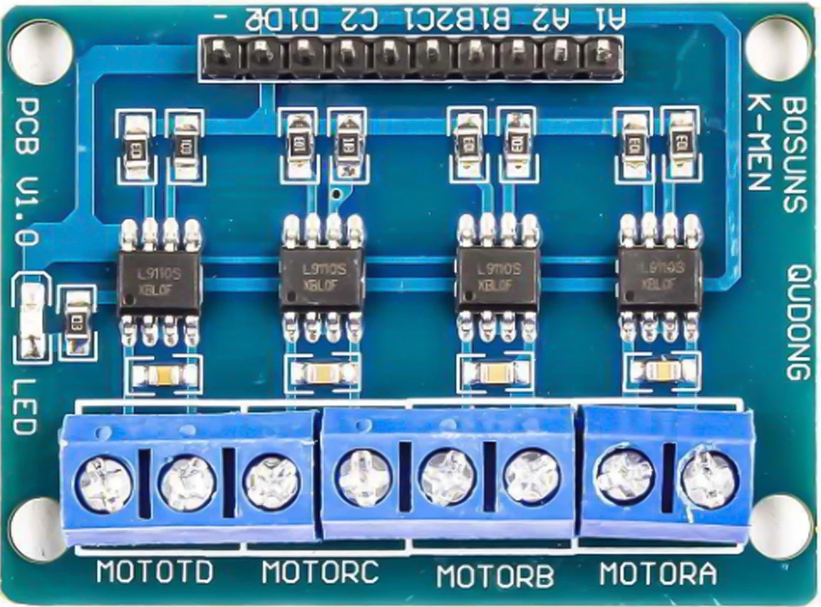
 Design with L9110S DC motor driver for 4 motors in Cirkit Designer
Introduction
The L9110S is a dual-channel DC motor driver designed to control up to four DC motors. Manufactured by Arduino/ESP32, this versatile component enables bidirectional control of motors, making it an excellent choice for robotics, automation, and other motor-driven applications. It features built-in protection against overcurrent and thermal overload, ensuring reliable operation in demanding environments.
Explore Projects Built with L9110S DC motor driver for 4 motors
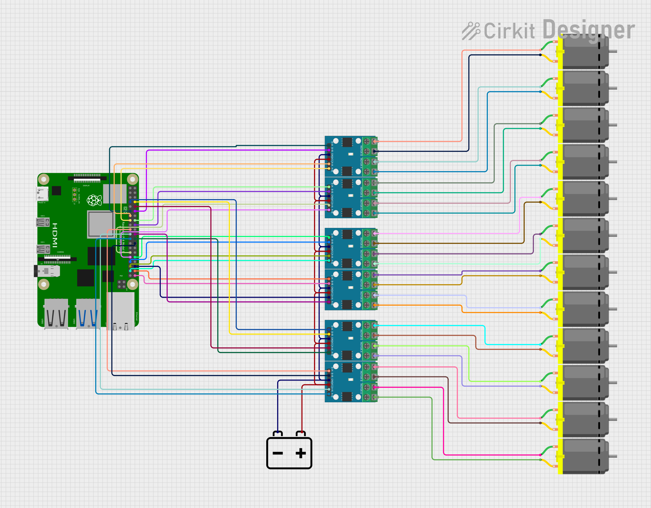 Open Project in Cirkit Designer
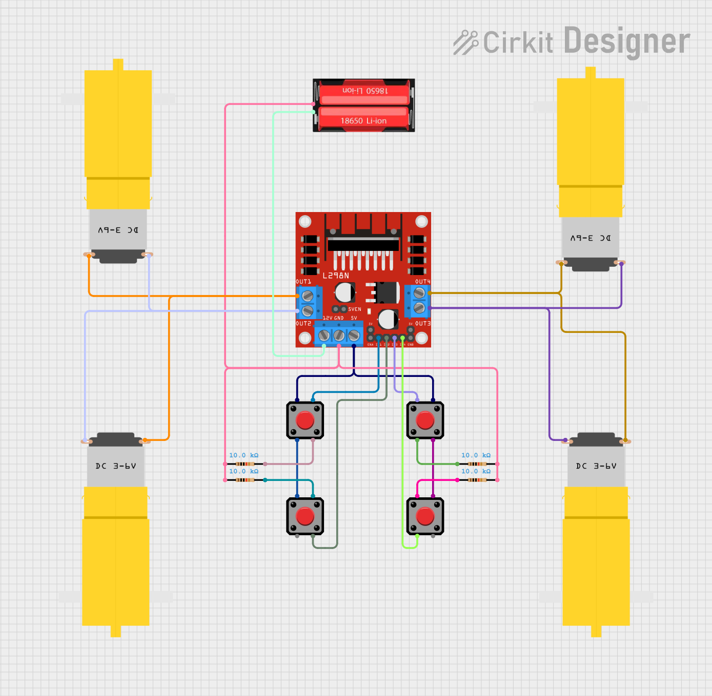 Open Project in Cirkit Designer
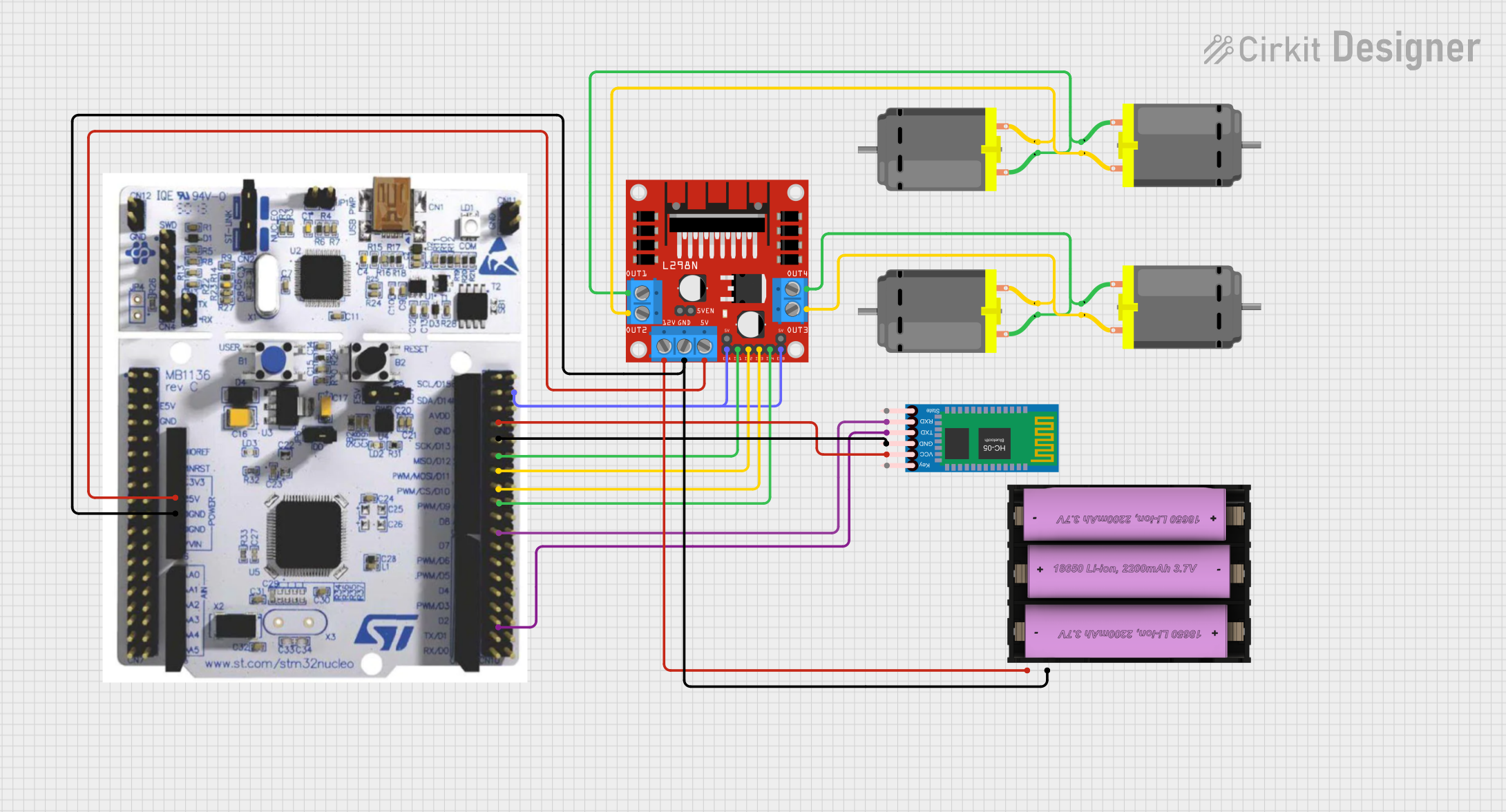 Open Project in Cirkit Designer
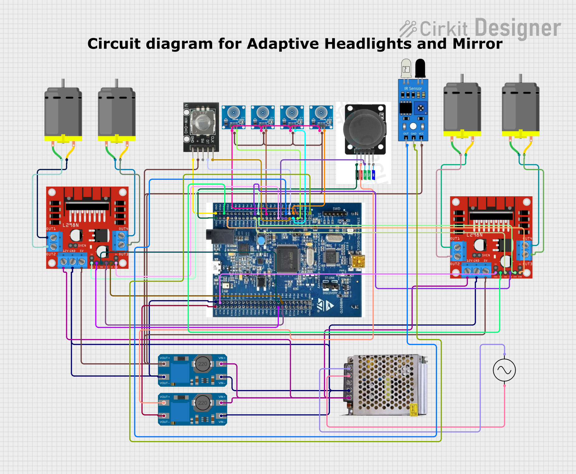 Open Project in Cirkit Designer
Explore Projects Built with L9110S DC motor driver for 4 motors
Open Project in Cirkit DesignerOpen Project in Cirkit DesignerOpen Project in Cirkit DesignerOpen Project in Cirkit DesignerCommon Applications
- Robotics (e.g., wheeled robots, robotic arms)
- Automated conveyor systems
- Smart home devices (e.g., motorized curtains or blinds)
- Educational projects involving motor control
- Small-scale industrial automation
Technical Specifications
The L9110S motor driver is designed to provide efficient and reliable motor control. Below are its key technical details:
Key Specifications
| Parameter | Value |
|---|---|
| Operating Voltage | 2.5V to 12V |
| Output Current (per channel) | 800mA (continuous) |
| Peak Output Current | 1.5A (short duration) |
| Number of Channels | 2 |
| Motor Control | Bidirectional (forward/reverse) |
| Protection Features | Overcurrent and thermal overload |
| Operating Temperature | -25°C to +85°C |
| Dimensions | 28mm x 21mm x 5mm |
Pin Configuration
The L9110S module has a simple pinout for easy integration into your projects. Below is the pin configuration:
| Pin Name | Description |
|---|---|
| A-IA | Input signal for Motor A (direction control) |
| A-IB | Input signal for Motor A (direction control) |
| B-IA | Input signal for Motor B (direction control) |
| B-IB | Input signal for Motor B (direction control) |
| VCC | Power supply for the module (2.5V to 12V) |
| GND | Ground connection |
| MA1 | Output to Motor A terminal 1 |
| MA2 | Output to Motor A terminal 2 |
| MB1 | Output to Motor B terminal 1 |
| MB2 | Output to Motor B terminal 2 |
Usage Instructions
The L9110S motor driver is straightforward to use in a circuit. Follow the steps below to integrate it into your project:
Connecting the L9110S
- Power Supply: Connect the
VCCpin to a power source (2.5V to 12V) and theGNDpin to ground. - Motor Connections:
- Connect the motor terminals to the
MA1,MA2,MB1, andMB2pins. - For controlling four motors, use two L9110S modules.
- Connect the motor terminals to the
- Control Signals:
- Connect the
A-IA,A-IB,B-IA, andB-IBpins to the GPIO pins of a microcontroller (e.g., Arduino or ESP32). - Use PWM signals to control motor speed and direction.
- Connect the
Example Arduino Code
Below is an example of how to control two DC motors using the L9110S and an Arduino UNO:
// Define motor control pins
const int motorA_IA = 3; // Motor A input A
const int motorA_IB = 5; // Motor A input B
const int motorB_IA = 6; // Motor B input A
const int motorB_IB = 9; // Motor B input B

void setup() {
  // Set motor control pins as outputs
  pinMode(motorA_IA, OUTPUT);
  pinMode(motorA_IB, OUTPUT);
  pinMode(motorB_IA, OUTPUT);
  pinMode(motorB_IB, OUTPUT);
}

void loop() {
  // Example: Rotate Motor A forward
  digitalWrite(motorA_IA, HIGH);
  digitalWrite(motorA_IB, LOW);

  // Example: Rotate Motor B backward
  digitalWrite(motorB_IA, LOW);
  digitalWrite(motorB_IB, HIGH);

  delay(2000); // Run motors for 2 seconds

  // Stop both motors
  digitalWrite(motorA_IA, LOW);
  digitalWrite(motorA_IB, LOW);
  digitalWrite(motorB_IA, LOW);
  digitalWrite(motorB_IB, LOW);

  delay(2000); // Wait for 2 seconds
}
Best Practices
- Use a decoupling capacitor (e.g., 100µF) across the power supply to reduce noise.
- Ensure the power supply voltage matches the motor's operating voltage.
- Avoid exceeding the maximum current rating to prevent damage to the module.
- Use heat sinks or proper ventilation if operating at high currents for extended periods.
Troubleshooting and FAQs
Common Issues and Solutions
Motors not spinning:
- Verify the power supply voltage and connections.
- Check the control signals from the microcontroller.
- Ensure the motor connections are secure.
Motors spinning in the wrong direction:
- Swap the connections of the motor terminals (
MA1andMA2, orMB1andMB2). - Adjust the logic levels of the control pins (
A-IA,A-IB,B-IA,B-IB).
- Swap the connections of the motor terminals (
Overheating of the module:
- Ensure the current drawn by the motors does not exceed the module's rating.
- Add a heat sink or improve ventilation around the module.
PWM control not working:
- Verify that the PWM pins on the microcontroller are correctly configured.
- Check the PWM frequency and duty cycle settings.
FAQs
Q: Can the L9110S control stepper motors?
A: Yes, the L9110S can control stepper motors by driving the coils in sequence. However, a dedicated stepper motor driver may provide better performance.
Q: Can I use the L9110S with a 3.3V microcontroller like the ESP32?
A: Yes, the L9110S is compatible with 3.3V logic levels, making it suitable for use with ESP32 and similar microcontrollers.
Q: How many motors can I control with one L9110S module?
A: One L9110S module can control two DC motors. To control four motors, you will need two modules.
By following this documentation, you can effectively integrate the L9110S motor driver into your projects and troubleshoot common issues with ease.