How to Use 12-Bit DAC: Examples, Pinouts, and Specs
Introduction
The MCP4726 is a 12-bit Digital-to-Analog Converter (DAC) manufactured by Microchip. It is capable of converting digital input signals into a corresponding analog output voltage. The MCP4726 is often used in applications requiring precise analog output, such as audio equipment, signal generation, and control systems. Its I2C interface allows for easy integration into microcontroller-based projects, including those using platforms like Arduino.
Explore Projects Built with 12-Bit DAC
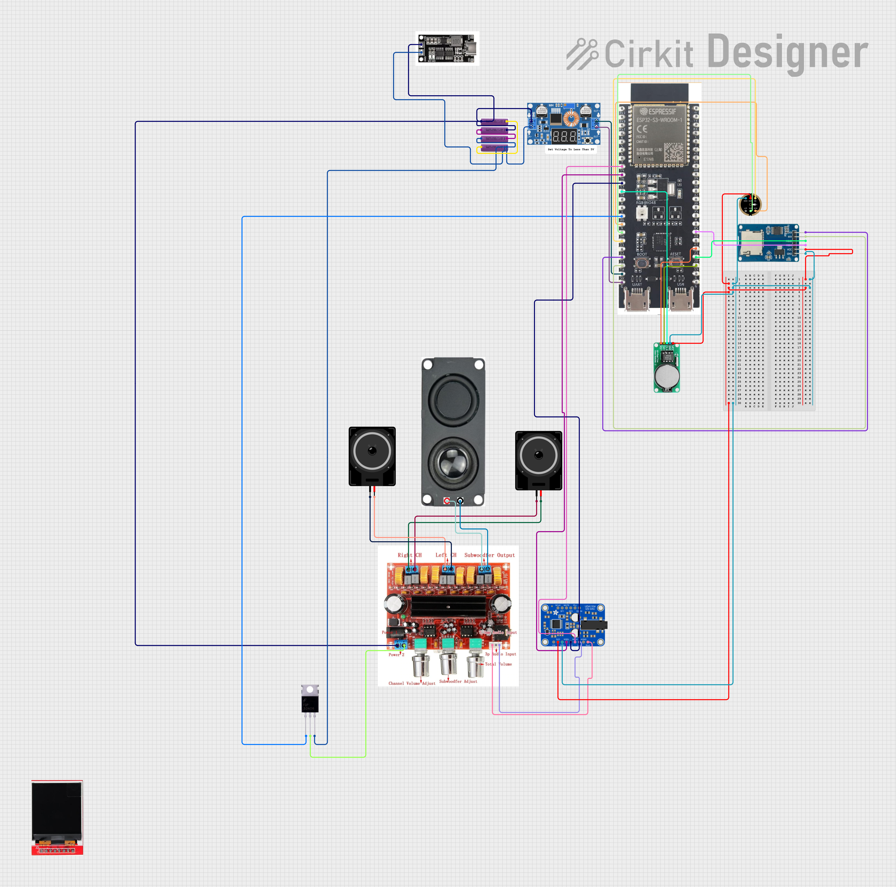

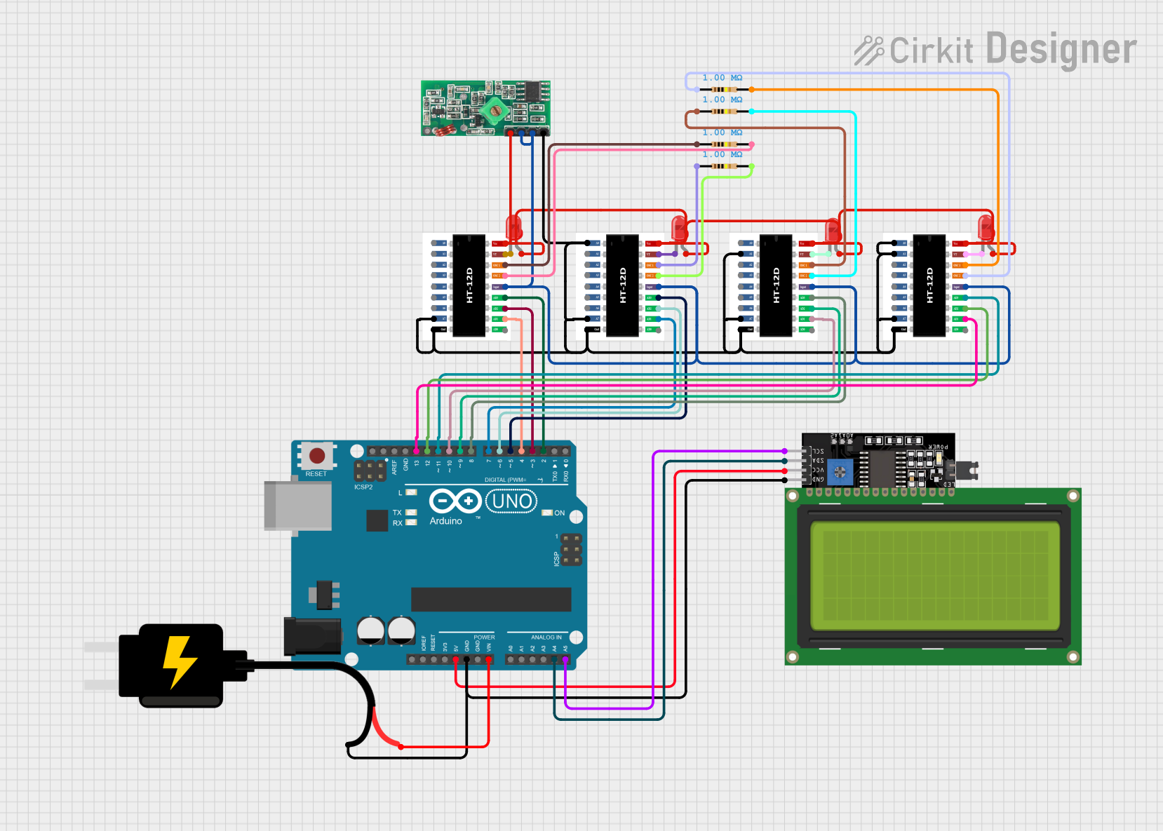
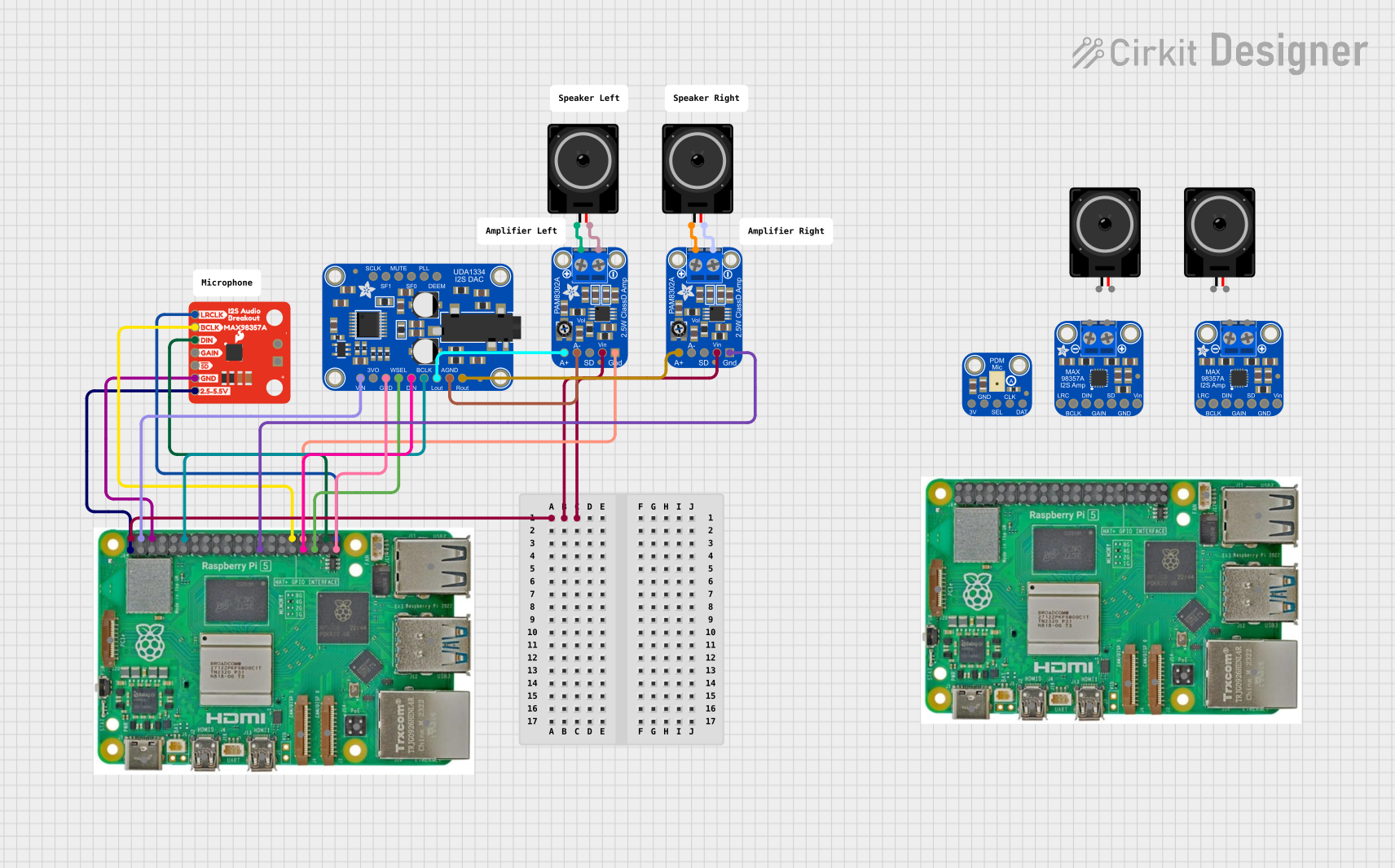
Explore Projects Built with 12-Bit DAC
Technical Specifications
Key Features
- 12-bit resolution
- Single channel output
- External voltage reference not required (internal reference)
- I2C interface with standard (100 kbps), fast (400 kbps), and high-speed (3.4 Mbps) modes
- Low-power consumption
- Extended temperature range: -40°C to +125°C
- 14-lead TSSOP and 8-lead MSOP packages available
Absolute Maximum Ratings
- Voltage on VDD relative to VSS: -0.3V to +6.0V
- Voltage on SDA, SCL relative to VSS: -0.3V to VDD +0.3V
- Maximum output current: 25 mA
Recommended Operating Conditions
- Supply voltage (VDD): 2.7V to 5.5V
- Ambient temperature: -40°C to +125°C
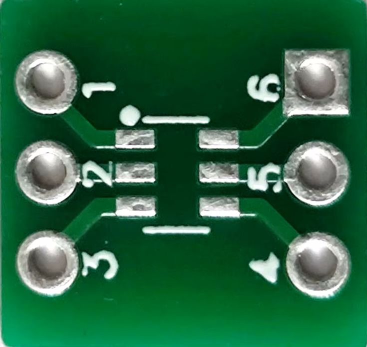
Pin Configuration and Descriptions
| Pin Number | Name | Description |
|---|---|---|
| 1 | VDD | Power supply pin (2.7V to 5.5V) |
| 2 | VOUT | Analog output voltage |
| 3 | VSS | Ground reference for power supply |
| 4 | SCL | Serial clock input for I2C interface |
| 5 | SDA | Serial data I/O for I2C interface |
| 6 | A0 | Address bit 0 (LSB for I2C address) |
| 7 | NC | No internal connection (can be left floating) |
| 8 | NC | No internal connection (can be left floating) |
Usage Instructions
Integration into a Circuit
To use the MCP4726 in a circuit:
- Connect VDD to a 2.7V to 5.5V power supply.
- Connect VSS to the ground of the power supply.
- Connect SCL and SDA to the I2C bus lines, with appropriate pull-up resistors.
- Connect A0 to either VSS or VDD to set the LSB of the I2C address.
- The VOUT pin will provide the analog output voltage.
Best Practices
- Place a decoupling capacitor (typically 0.1 µF) close to the VDD pin to filter out noise.
- Ensure that the I2C bus lines have pull-up resistors, typically 4.7 kΩ to 10 kΩ.
- Avoid running analog signal lines near high-frequency digital lines to minimize noise coupling.
Example Code for Arduino UNO
#include <Wire.h>

// MCP4726 default I2C address (A0 pin connected to GND)
#define MCP4726_ADDR 0x60

void setup() {
  Wire.begin(); // Join I2C bus
  Serial.begin(9600); // Start serial communication for debugging
}

void loop() {
  // Set DAC output to mid-scale
  setDACValue(2048); // 12-bit DAC, mid-scale is 2048
  delay(1000); // Wait for 1 second
}

void setDACValue(unsigned int value) {
  Wire.beginTransmission(MCP4726_ADDR); // Start I2C transmission
  Wire.write(0x40); // Control byte, sets the DAC register
  Wire.write(value >> 4); // Upper data bits (D11.D10.D9.D8.D7.D6.D5.D4)
  Wire.write((value & 15) << 4); // Lower data bits (D3.D2.D1.D0.x.x.x.x)
  Wire.endTransmission(); // End I2C transmission

  Serial.print("DAC set to: "); // Debug output
  Serial.println(value);
}
Troubleshooting and FAQs
Common Issues
- No Output Voltage: Ensure that the VDD and VSS are properly connected and that the power supply is within the recommended operating range. Check the I2C connections and address settings.
- Inaccurate Output Voltage: Verify that the input value is correct and that there is no noise on the I2C lines. Check for proper grounding and stable power supply.
- I2C Communication Failure: Ensure pull-up resistors are installed on the SCL and SDA lines. Check for correct I2C address and absence of bus contention.
FAQs
Q: Can the MCP4726 output negative voltages? A: No, the MCP4726 is designed to output voltages from 0V to VDD.
Q: How do I change the I2C address of the MCP4726? A: The LSB of the I2C address can be changed by connecting the A0 pin to VDD or VSS. The rest of the address is fixed.
Q: What is the resolution of the MCP4726? A: The MCP4726 has a 12-bit resolution, which means it can produce 4096 (2^12) discrete voltage levels.
Q: Is it necessary to use an external voltage reference with the MCP4726? A: No, the MCP4726 has an internal voltage reference. However, for applications requiring higher precision, an external reference can be used.
Q: How do I reset the MCP4726 to its default settings? A: The MCP4726 does not have a specific reset pin, but you can reset it by power cycling the device or by sending a software reset command via the I2C interface.