How to Use Closed Loop Stepper Drive: Examples, Pinouts, and Specs
Introduction
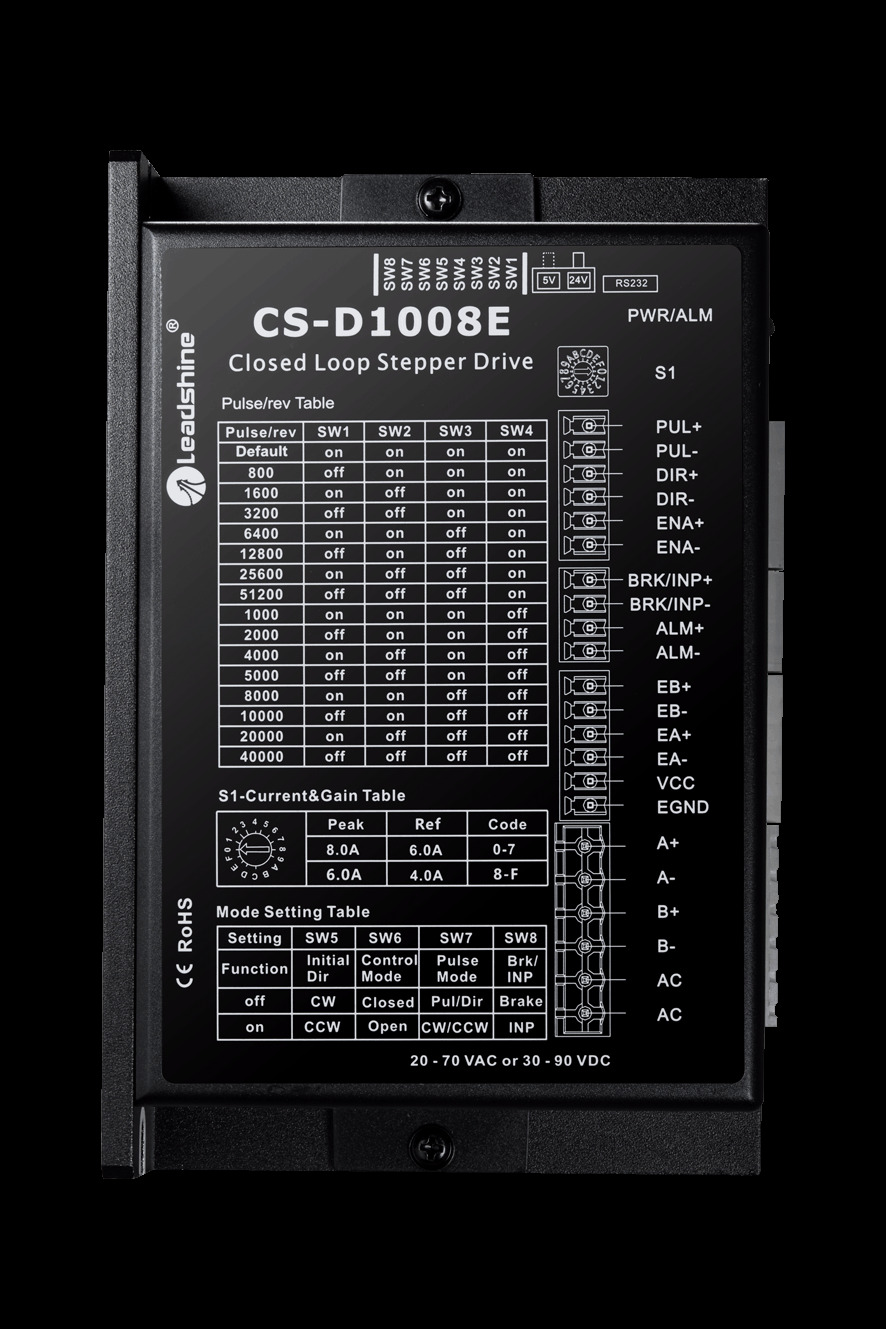
The Leadshine CS-D1008E is a closed-loop stepper drive designed to enhance the performance of stepper motors by incorporating feedback control. Unlike traditional open-loop stepper systems, this drive uses an encoder to monitor the motor's position and speed, ensuring precise control and eliminating issues such as missed steps, motor stalling, and excessive heat generation. It is ideal for applications requiring high accuracy, smooth motion, and reliable operation.
Explore Projects Built with Closed Loop Stepper Drive
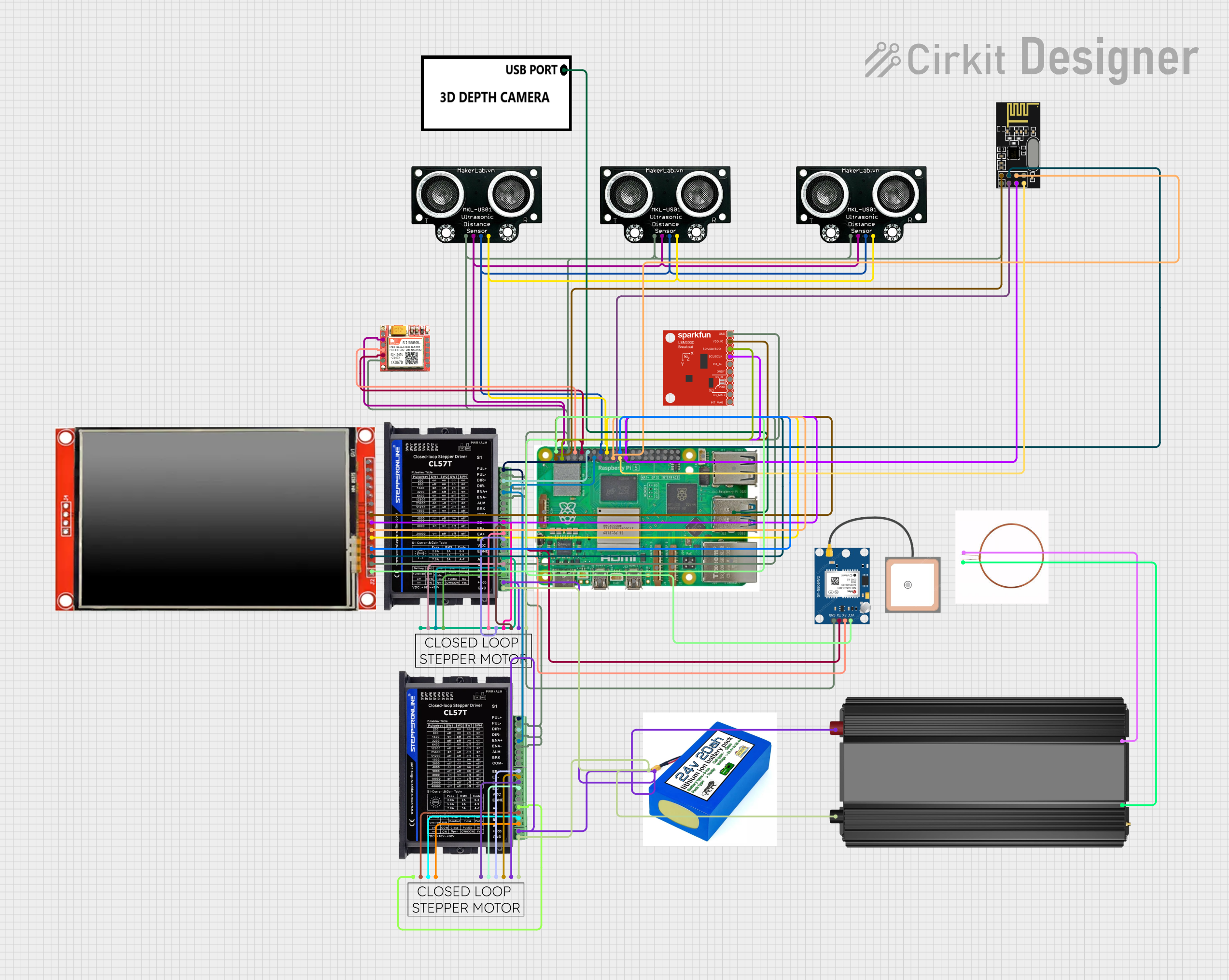
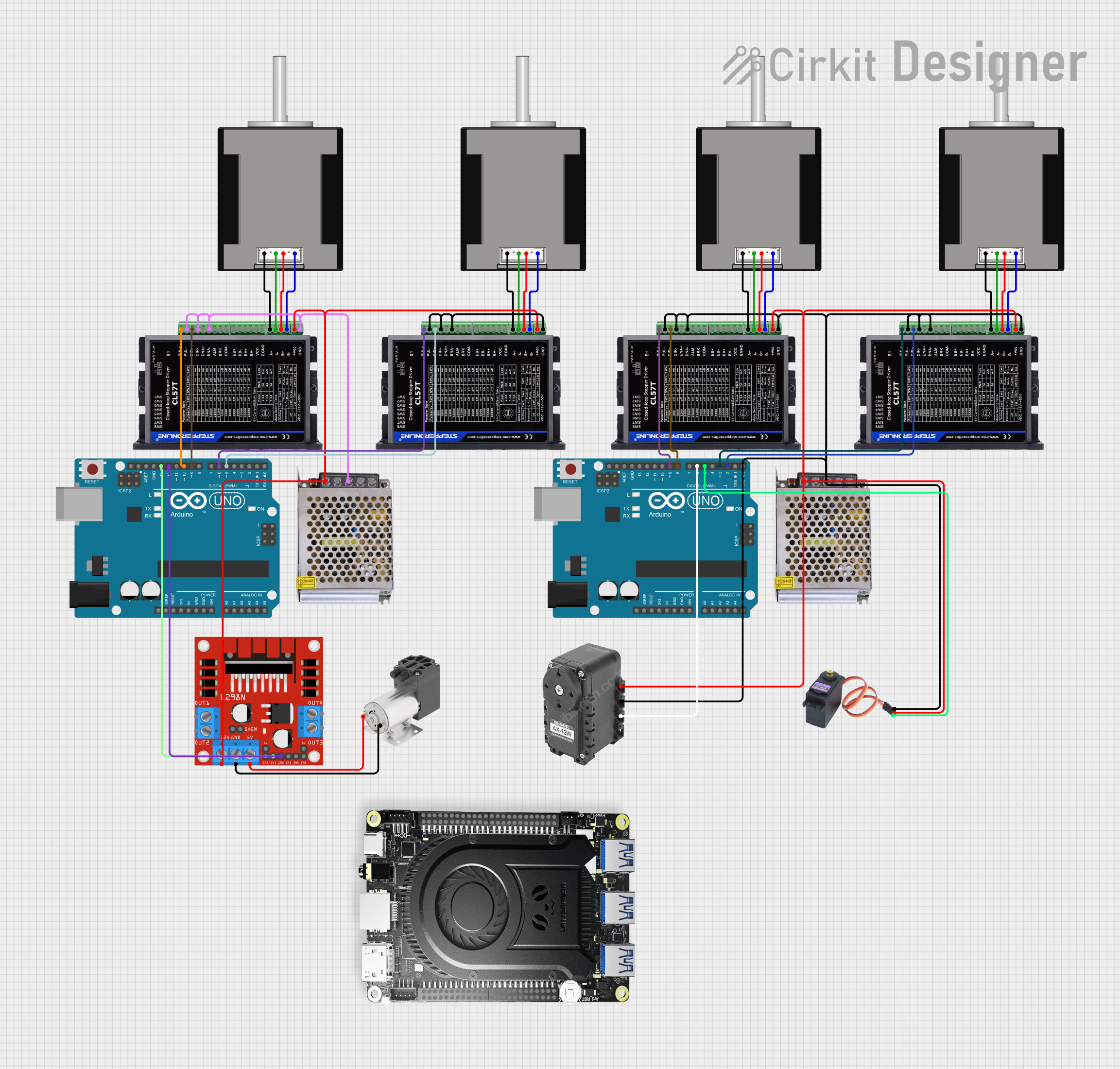
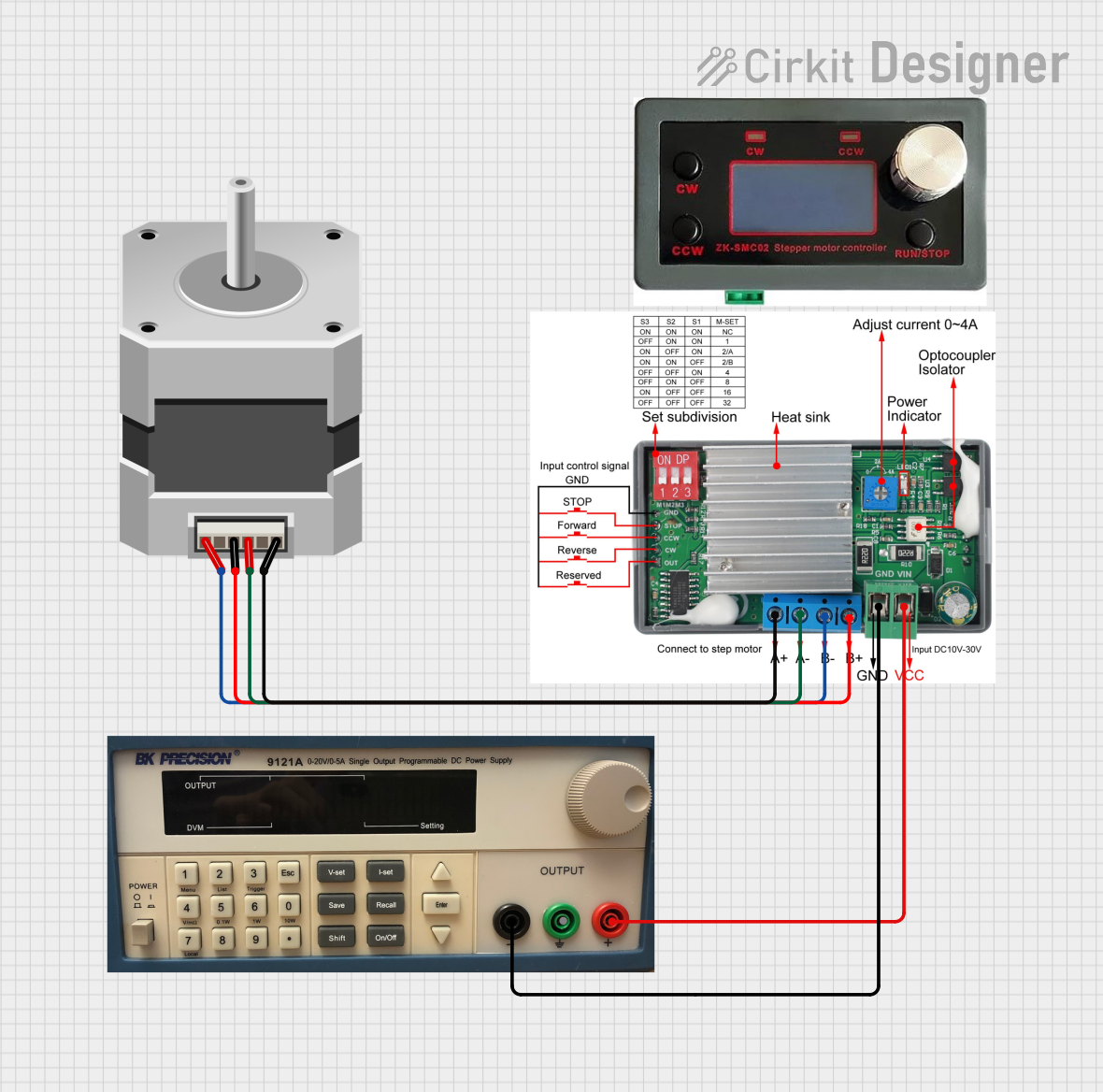
Explore Projects Built with Closed Loop Stepper Drive
Common Applications
- CNC machines and 3D printers
- Robotics and automation systems
- Medical equipment
- Laser cutters and engraving machines
- Packaging and labeling machinery
Technical Specifications
The following table outlines the key technical specifications of the Leadshine CS-D1008E:
| Parameter | Value |
|---|---|
| Input Voltage | 24-70 VDC |
| Output Current | 1.0-8.0 A (peak) |
| Control Signal Type | Pulse/Direction or CW/CCW |
| Microstep Resolution | Configurable, up to 51,200 steps/rev |
| Feedback Type | Incremental encoder (1000-line) |
| Communication Interface | RS232 |
| Operating Temperature | 0°C to 50°C |
| Dimensions | 151 x 97 x 48 mm |
| Weight | 0.6 kg |
Pin Configuration and Descriptions
The CS-D1008E features multiple connectors for power, motor, encoder, and control signals. Below is the pin configuration:
Control Signal Connector (P1)
| Pin | Name | Description |
|---|---|---|
| 1 | PUL+ | Pulse signal input (positive) |
| 2 | PUL- | Pulse signal input (negative) |
| 3 | DIR+ | Direction signal input (positive) |
| 4 | DIR- | Direction signal input (negative) |
| 5 | ENA+ | Enable signal input (positive) |
| 6 | ENA- | Enable signal input (negative) |
Power and Motor Connector (P2)
| Pin | Name | Description |
|---|---|---|
| 1 | V+ | Power supply positive terminal (24-70 VDC) |
| 2 | V- | Power supply negative terminal |
| 3 | A+ | Motor winding A+ |
| 4 | A- | Motor winding A- |
| 5 | B+ | Motor winding B+ |
| 6 | B- | Motor winding B- |
Encoder Connector (P3)
| Pin | Name | Description |
|---|---|---|
| 1 | EA+ | Encoder channel A (positive) |
| 2 | EA- | Encoder channel A (negative) |
| 3 | EB+ | Encoder channel B (positive) |
| 4 | EB- | Encoder channel B (negative) |
| 5 | VCC | Encoder power supply (5V) |
| 6 | GND | Encoder ground |
Usage Instructions
How to Use the CS-D1008E in a Circuit
- Power Supply: Connect a DC power supply (24-70 VDC) to the V+ and V- terminals on the P2 connector. Ensure the power supply can provide sufficient current for the motor.
- Motor Connection: Connect the stepper motor windings to the A+, A-, B+, and B- terminals on the P2 connector.
- Encoder Connection: Connect the encoder wires to the P3 connector, ensuring proper polarity for channels A and B.
- Control Signals: Connect the pulse, direction, and enable signals from your controller (e.g., Arduino, PLC) to the P1 connector.
- Configuration: Use the RS232 interface to configure parameters such as microstep resolution, current limits, and control mode using the Leadshine configuration software.
Important Considerations
- Power Supply: Use a regulated DC power supply within the specified voltage range to avoid damage.
- Signal Integrity: Use shielded cables for control and encoder signals to minimize noise interference.
- Heat Dissipation: Mount the drive on a metal surface or use a heatsink to ensure proper heat dissipation.
- Motor Compatibility: Ensure the stepper motor is compatible with the drive's current and voltage ratings.
Example: Connecting to an Arduino UNO
Below is an example of how to control the CS-D1008E using an Arduino UNO:
Circuit Diagram
- Connect the Arduino's digital pins to the PUL+, DIR+, and ENA+ pins on the drive.
- Connect the PUL-, DIR-, and ENA- pins to the Arduino's GND.
Arduino Code
// Define control pins
const int pulsePin = 2;  // Pulse signal pin
const int dirPin = 3;    // Direction signal pin
const int enablePin = 4; // Enable signal pin

void setup() {
  // Set pins as outputs
  pinMode(pulsePin, OUTPUT);
  pinMode(dirPin, OUTPUT);
  pinMode(enablePin, OUTPUT);

  // Enable the stepper drive
  digitalWrite(enablePin, HIGH); // HIGH enables the drive
}

void loop() {
  // Set direction
  digitalWrite(dirPin, HIGH); // HIGH for one direction, LOW for the other

  // Generate pulses to move the motor
  for (int i = 0; i < 200; i++) { // 200 steps for one revolution (example)
    digitalWrite(pulsePin, HIGH);
    delayMicroseconds(500); // Adjust for speed
    digitalWrite(pulsePin, LOW);
    delayMicroseconds(500);
  }

  delay(1000); // Wait for 1 second before reversing direction

  // Reverse direction
  digitalWrite(dirPin, LOW);
  for (int i = 0; i < 200; i++) {
    digitalWrite(pulsePin, HIGH);
    delayMicroseconds(500);
    digitalWrite(pulsePin, LOW);
    delayMicroseconds(500);
  }

  delay(1000); // Wait for 1 second before repeating
}
Troubleshooting and FAQs
Common Issues and Solutions
Motor Not Moving
- Cause: Incorrect wiring or loose connections.
- Solution: Double-check all connections, especially the motor and control signal wiring.
Motor Stalling or Missing Steps
- Cause: Insufficient power supply or incorrect microstep settings.
- Solution: Ensure the power supply meets the voltage and current requirements. Adjust the microstep resolution to match the application.
Excessive Heat
- Cause: Overcurrent or poor heat dissipation.
- Solution: Reduce the current limit in the configuration software and ensure proper ventilation.
Encoder Feedback Error
- Cause: Incorrect encoder wiring or signal noise.
- Solution: Verify the encoder connections and use shielded cables.
FAQs
Q: Can I use the CS-D1008E with a NEMA 23 stepper motor?
A: Yes, as long as the motor's current and voltage ratings are within the drive's specifications.Q: What is the maximum pulse frequency supported?
A: The CS-D1008E supports a maximum pulse frequency of 200 kHz.Q: Can I use this drive with a PLC?
A: Yes, the drive supports standard pulse and direction signals compatible with most PLCs.Q: How do I configure the drive parameters?
A: Use the Leadshine configuration software via the RS232 interface to adjust settings such as microstep resolution and current limits.