How to Use ky-040: Examples, Pinouts, and Specs
Introduction
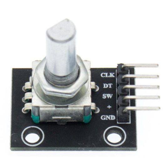
The KY-040 is a rotary encoder module designed for precise control of position and rotation. Unlike potentiometers, which provide an absolute position, the KY-040 generates incremental signals that allow users to track relative movement. It features a knob that can be rotated in either direction and a push-button switch for additional functionality. The module is widely used in applications requiring user input, such as volume control, menu navigation, and motor control.
Explore Projects Built with ky-040
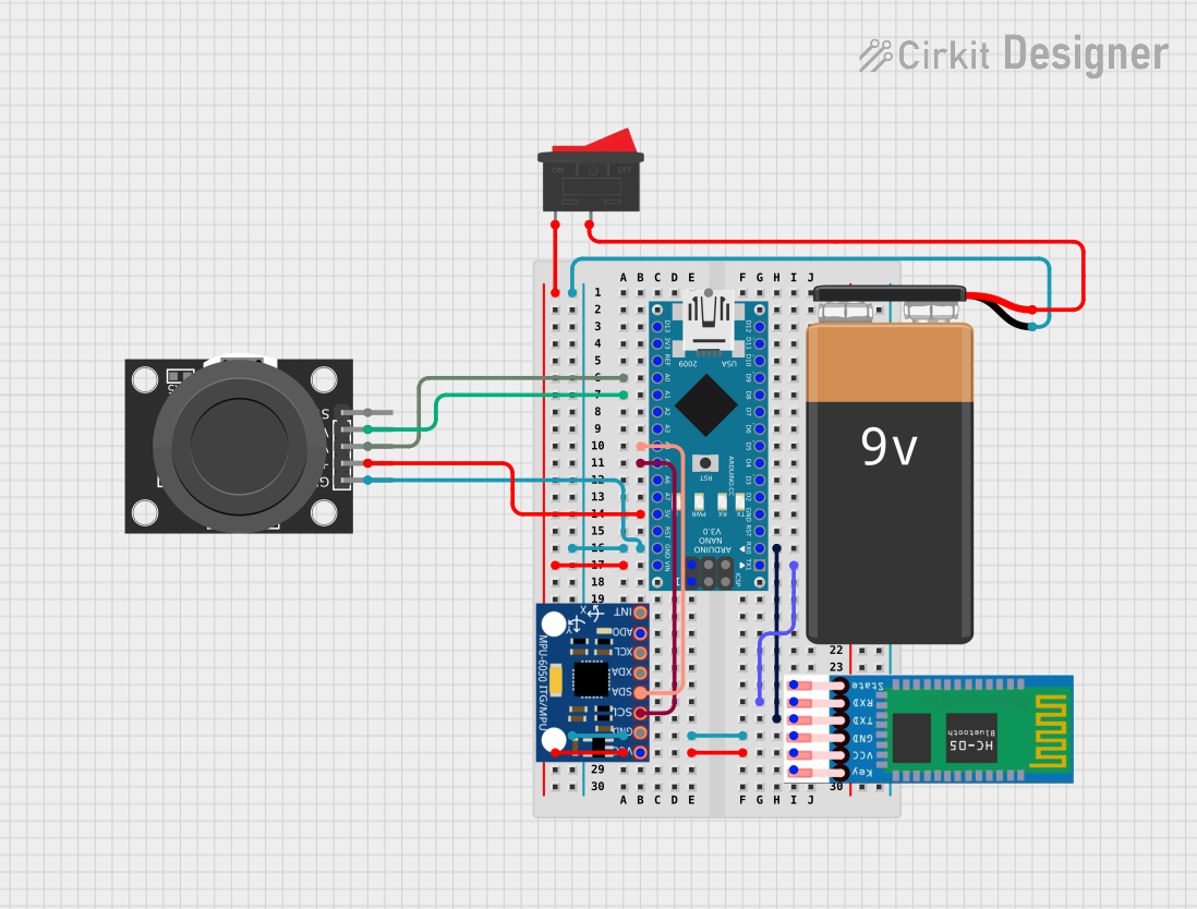

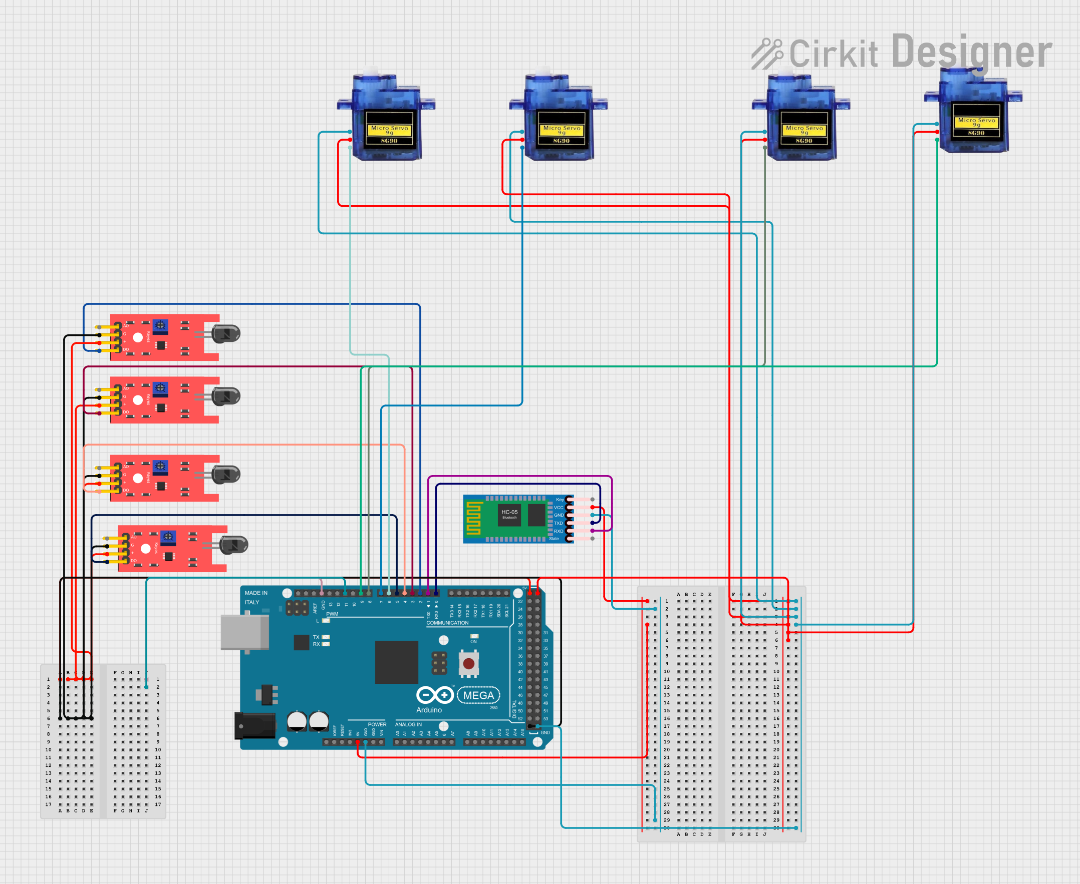
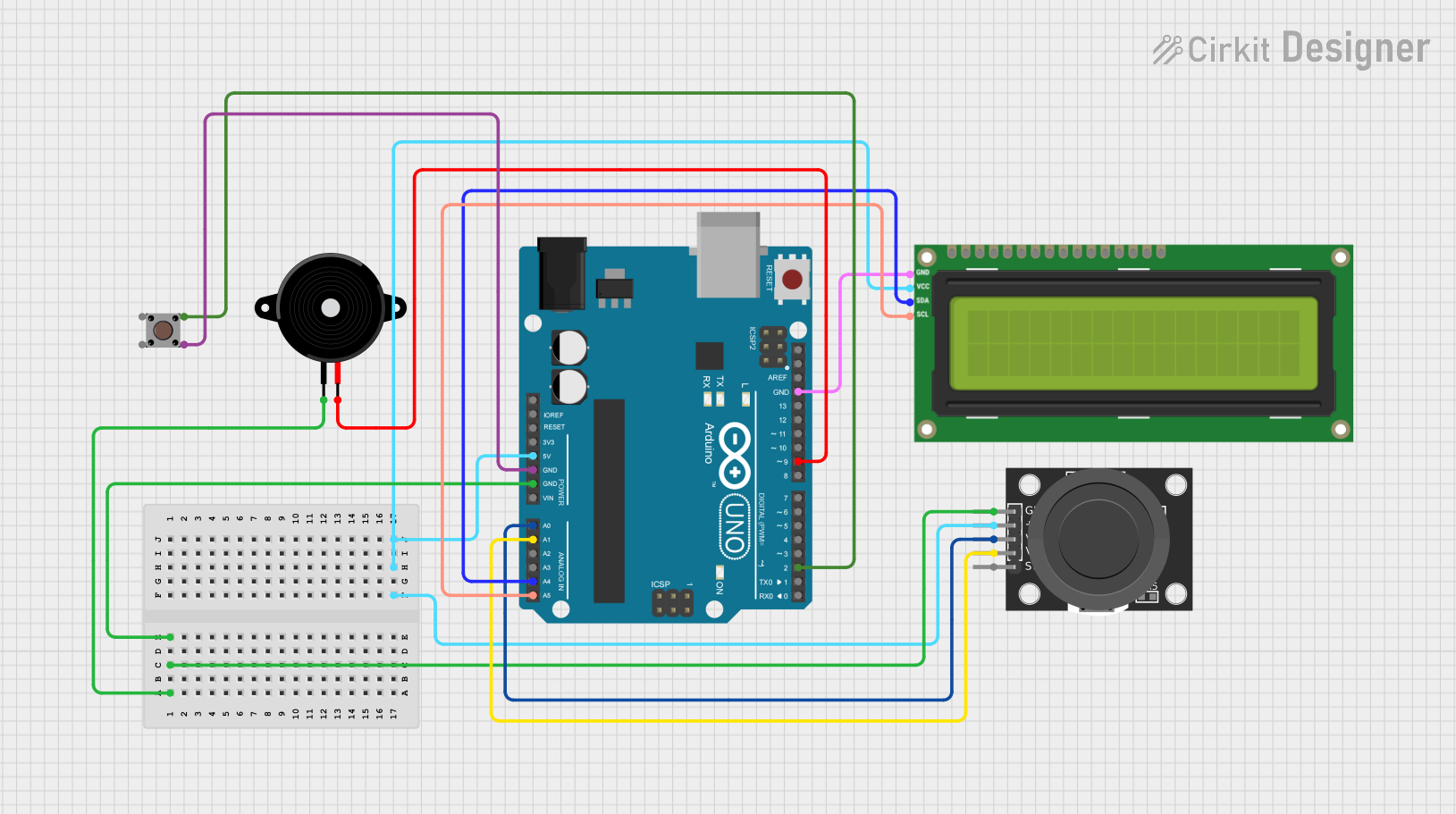
Explore Projects Built with ky-040
Common Applications
- Volume and brightness adjustment
- Menu navigation in embedded systems
- Motor speed and position control
- Robotics and automation systems
- DIY electronics projects
Technical Specifications
The KY-040 rotary encoder module has the following key specifications:
| Parameter | Value |
|---|---|
| Operating Voltage | 3.3V to 5V |
| Output Type | Digital (Incremental) |
| Number of Pulses per Revolution | 20 |
| Push-Button Switch | Integrated |
| Dimensions | 32mm x 19mm x 30mm |
Pin Configuration
The KY-040 module has 5 pins, as described in the table below:
| Pin | Label | Description |
|---|---|---|
| 1 | GND | Ground connection |
| 2 | + | Power supply (3.3V to 5V) |
| 3 | SW | Push-button switch output (active LOW) |
| 4 | DT | Data signal (used to determine rotation direction when combined with CLK) |
| 5 | CLK | Clock signal (used to generate pulses during rotation) |
Usage Instructions
The KY-040 rotary encoder is easy to integrate into circuits and works seamlessly with microcontrollers like the Arduino UNO. Below are the steps to use the module effectively:
Connecting the KY-040 to an Arduino UNO
- Connect the GND pin of the KY-040 to the GND pin on the Arduino.
- Connect the + pin of the KY-040 to the 5V pin on the Arduino.
- Connect the CLK pin to a digital input pin on the Arduino (e.g., pin 2).
- Connect the DT pin to another digital input pin on the Arduino (e.g., pin 3).
- Connect the SW pin to a digital input pin (e.g., pin 4) if you want to use the push-button functionality.
Sample Arduino Code
The following code demonstrates how to read the rotation direction and button press from the KY-040 module:
// Define pins for the KY-040 rotary encoder
#define CLK 2  // Clock pin
#define DT 3   // Data pin
#define SW 4   // Switch pin

int lastStateCLK;  // To store the previous state of the CLK pin
int currentStateCLK;  // To store the current state of the CLK pin
int counter = 0;  // Counter to track rotation
bool buttonPressed = false;  // Flag for button press

void setup() {
  pinMode(CLK, INPUT);  // Set CLK pin as input
  pinMode(DT, INPUT);   // Set DT pin as input
  pinMode(SW, INPUT_PULLUP);  // Set SW pin as input with pull-up resistor

  // Read the initial state of the CLK pin
  lastStateCLK = digitalRead(CLK);

  // Initialize serial communication for debugging
  Serial.begin(9600);
}

void loop() {
  // Read the current state of the CLK pin
  currentStateCLK = digitalRead(CLK);

  // Check if the state of CLK has changed
  if (currentStateCLK != lastStateCLK) {
    // Read the state of the DT pin
    int stateDT = digitalRead(DT);

    // Determine rotation direction
    if (stateDT != currentStateCLK) {
      counter++;  // Clockwise rotation
    } else {
      counter--;  // Counterclockwise rotation
    }

    // Print the counter value to the serial monitor
    Serial.print("Counter: ");
    Serial.println(counter);
  }

  // Update the last state of the CLK pin
  lastStateCLK = currentStateCLK;

  // Check if the button is pressed
  if (digitalRead(SW) == LOW) {
    if (!buttonPressed) {
      Serial.println("Button Pressed!");
      buttonPressed = true;
    }
  } else {
    buttonPressed = false;
  }
}
Important Considerations
- Debouncing: The KY-040 may produce noisy signals during rotation or button presses. Use software debouncing techniques or external capacitors to filter out noise.
- Power Supply: Ensure the module is powered within its operating voltage range (3.3V to 5V).
- Pull-Up Resistors: The push-button switch requires a pull-up resistor. The Arduino's internal pull-up resistor can be enabled using
INPUT_PULLUP.
Troubleshooting and FAQs
Common Issues
No Response from the Encoder
- Solution: Verify all connections, especially the GND and power pins. Ensure the CLK and DT pins are connected to the correct digital input pins on the microcontroller.
Incorrect Rotation Direction
- Solution: Swap the connections of the CLK and DT pins on the microcontroller.
Button Not Working
- Solution: Ensure the SW pin is connected to a digital input pin and configured with a pull-up resistor.
Noisy or Erratic Readings
- Solution: Implement software debouncing or add a small capacitor (e.g., 0.1µF) between the CLK/DT pins and GND to filter noise.
FAQs
Can the KY-040 be used with 3.3V systems?
- Yes, the KY-040 is compatible with both 3.3V and 5V systems.
What is the resolution of the KY-040?
- The KY-040 generates 20 pulses per revolution, but the effective resolution depends on how the signals are processed (e.g., full-step or half-step decoding).
Can I use the KY-040 for absolute position tracking?
- No, the KY-040 is an incremental encoder and only tracks relative movement. For absolute position tracking, additional circuitry or sensors are required.
Is the KY-040 suitable for high-speed applications?
- The KY-040 is designed for manual input and may not perform well in high-speed applications due to signal noise and mechanical limitations.