How to Use LM1084-3.3: Examples, Pinouts, and Specs
Introduction
The LM1084-3.3 is a low dropout (LDO) voltage regulator designed to provide a stable output voltage of 3.3V. Manufactured under the part ID LM1084-3.3-5A, this component is capable of delivering up to 5A of output current. Its low dropout voltage makes it ideal for applications requiring high power efficiency and minimal heat dissipation.
Explore Projects Built with LM1084-3.3


Explore Projects Built with LM1084-3.3
Common Applications and Use Cases
- Power supply regulation for microcontrollers, sensors, and other low-voltage devices
- Battery-powered systems where efficiency is critical
- Industrial and consumer electronics requiring a stable 3.3V power source
- Post-regulation for switching power supplies
Technical Specifications
Key Technical Details
| Parameter | Value |
|---|---|
| Output Voltage | 3.3V |
| Maximum Output Current | 5A |
| Dropout Voltage | 1.1V (typical at 5A load) |
| Input Voltage Range | 4.5V to 29V |
| Quiescent Current | 5mA (typical) |
| Operating Temperature | -40°C to +125°C |
| Package Type | TO-220, TO-263 (D2PAK) |
| Manufacturer | me |
| Part ID | LM1084-3.3-5A |
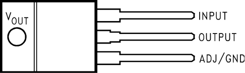
Pin Configuration and Descriptions
The LM1084-3.3 is typically available in a TO-220 or TO-263 (D2PAK) package. Below is the pinout description:
TO-220 Package Pinout
| Pin Number | Pin Name | Description |
|---|---|---|
| 1 | ADJ/GND | Ground (GND) for fixed versions like LM1084-3.3 |
| 2 | VOUT | Regulated 3.3V output |
| 3 | VIN | Input voltage (4.5V to 29V) |
| Tab | VOUT | Connected to the output voltage internally |
TO-263 (D2PAK) Package Pinout
| Pin Number | Pin Name | Description |
|---|---|---|
| 1 | ADJ/GND | Ground (GND) for fixed versions like LM1084-3.3 |
| 2 | VOUT | Regulated 3.3V output |
| 3 | VIN | Input voltage (4.5V to 29V) |
| Tab | VOUT | Connected to the output voltage internally |
Usage Instructions
How to Use the LM1084-3.3 in a Circuit
- Input Voltage Requirements: Ensure the input voltage (VIN) is at least 4.5V and no more than 29V. For optimal performance, VIN should be at least 1.5V higher than the output voltage (3.3V).
- Output Capacitor: Connect a low ESR capacitor (e.g., 10µF tantalum or 47µF aluminum electrolytic) between the VOUT pin and ground to ensure stability.
- Input Capacitor: Place a capacitor (e.g., 10µF) between the VIN pin and ground to filter input noise and improve transient response.
- Thermal Management: Use a heatsink or ensure proper PCB thermal design to dissipate heat, especially when operating at high currents (e.g., 5A).
- Wiring: Minimize the length of wires or PCB traces between the input/output pins and the capacitors to reduce noise and improve stability.
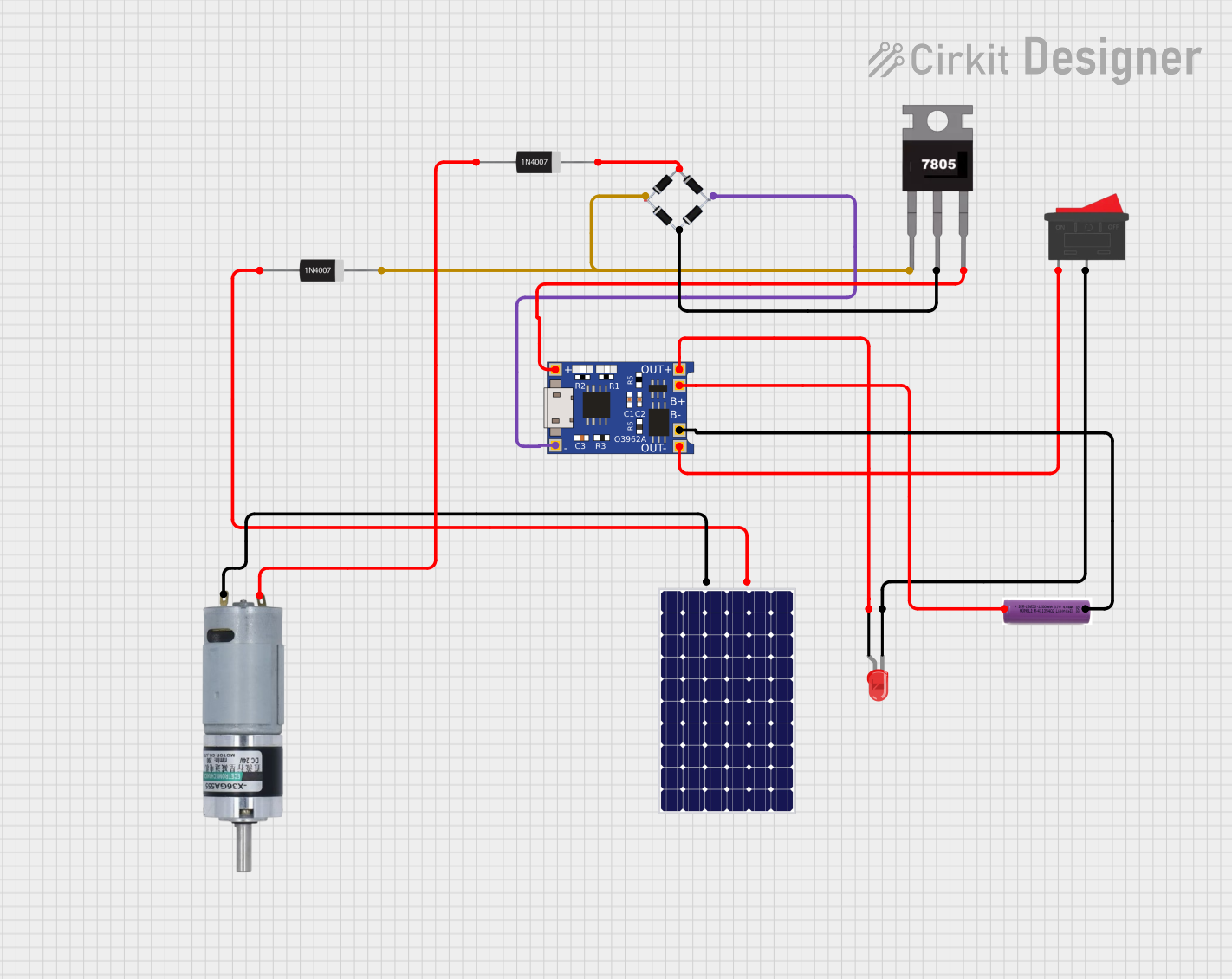
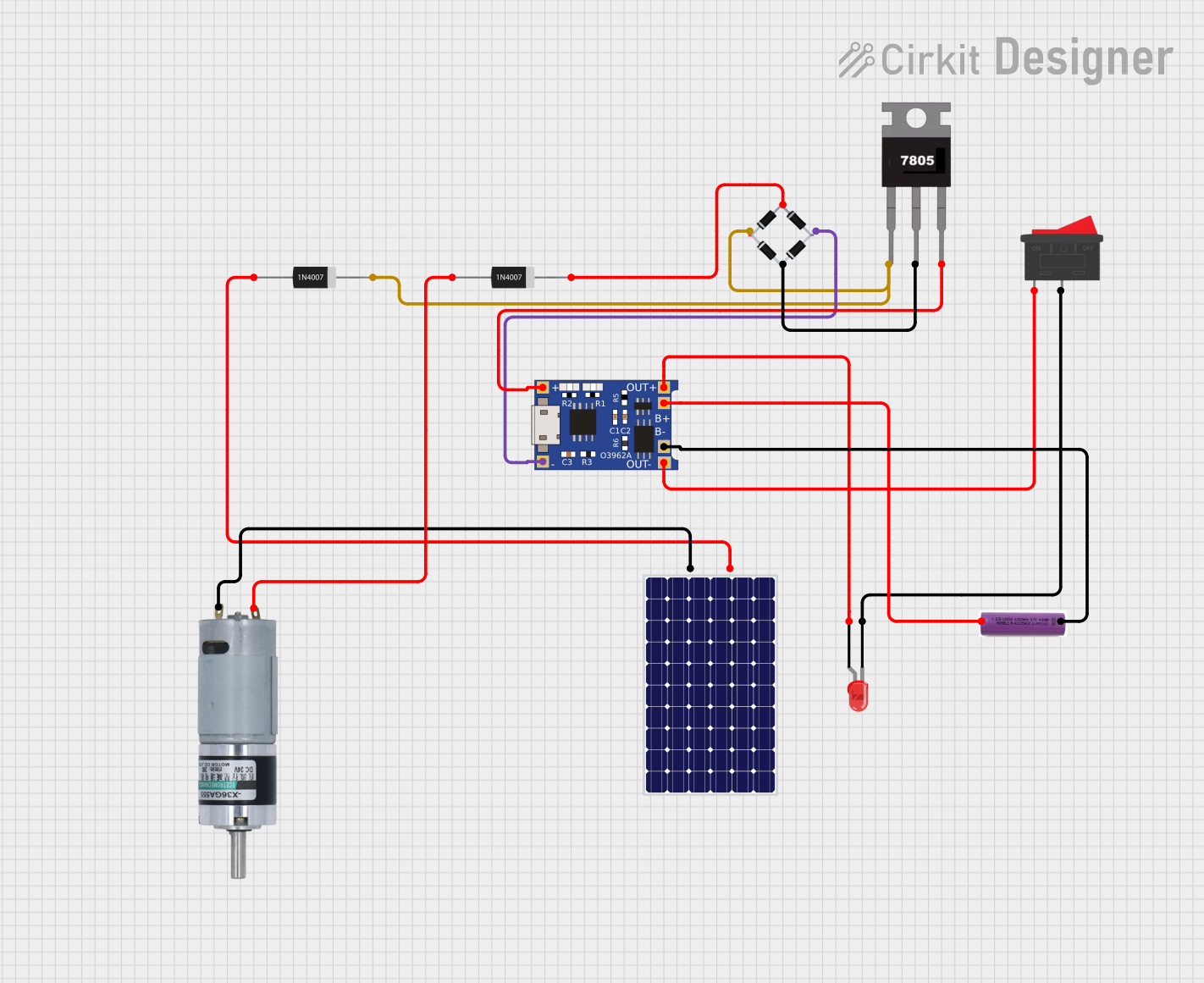
Example Circuit
Below is a basic application circuit for the LM1084-3.3:
   +--------------------+
   |                    |
   |   LM1084-3.3       |
   |                    |
   |   +----+----+----+ |
   |   | VIN| VOUT| GND| |
   |   +----+----+----+ |
   +--------------------+
        |      |     |
        |      |     +---> GND
        |      +----------> 3.3V Output
        +-----------------> Input Voltage (4.5V to 29V)
Arduino UNO Example
The LM1084-3.3 can be used to power an Arduino UNO by providing a stable 3.3V supply. Below is an example of how to connect it:
- Connect the VIN pin of the LM1084-3.3 to a 5V-12V power source.
- Connect the VOUT pin to the 3.3V pin of the Arduino UNO.
- Connect the GND pin to the ground of the Arduino UNO.
Arduino Code Example
// Example: Reading a sensor powered by LM1084-3.3
// Ensure the sensor operates at 3.3V and is connected to the Arduino

const int sensorPin = A0; // Analog pin connected to the sensor output
int sensorValue = 0;      // Variable to store the sensor reading

void setup() {
  Serial.begin(9600); // Initialize serial communication
}

void loop() {
  sensorValue = analogRead(sensorPin); // Read the sensor value
  Serial.print("Sensor Value: ");
  Serial.println(sensorValue); // Print the sensor value to the Serial Monitor
  delay(1000); // Wait for 1 second before the next reading
}
Important Considerations and Best Practices
- Thermal Protection: The LM1084-3.3 includes thermal shutdown protection. However, ensure proper heat dissipation to avoid triggering this feature.
- Current Limiting: The regulator has built-in current limiting. Do not exceed the maximum output current of 5A.
- Capacitor Selection: Use low ESR capacitors to maintain stability and reduce output noise.
- Reverse Polarity Protection: The LM1084-3.3 does not include reverse polarity protection. Use a diode in series with the input if reverse polarity is a concern.
Troubleshooting and FAQs
Common Issues and Solutions
Output Voltage is Incorrect
- Cause: Insufficient input voltage or incorrect capacitor selection.
- Solution: Ensure VIN is at least 1.5V higher than VOUT and use the recommended capacitors.
Regulator Overheating
- Cause: Excessive power dissipation or inadequate thermal management.
- Solution: Use a heatsink or improve PCB thermal design. Reduce the load current if possible.
Output Voltage is Unstable
- Cause: Missing or incorrect output capacitor.
- Solution: Use a low ESR capacitor (e.g., 10µF tantalum or 47µF aluminum electrolytic) on the output.
No Output Voltage
- Cause: Incorrect wiring or damaged component.
- Solution: Verify the connections and ensure the input voltage is within the specified range.
FAQs
Q: Can the LM1084-3.3 be used with a 12V input?
A: Yes, the LM1084-3.3 can accept input voltages up to 29V. Ensure proper heat dissipation when using higher input voltages.
Q: What happens if the load exceeds 5A?
A: The LM1084-3.3 includes current limiting and will reduce the output current to protect itself. Prolonged overcurrent conditions may trigger thermal shutdown.
Q: Can I use ceramic capacitors with the LM1084-3.3?
A: While ceramic capacitors can be used, ensure they have a low ESR and are appropriately rated for the application. Tantalum or aluminum electrolytic capacitors are generally recommended for stability.