Cirkit Designer
Your all-in-one circuit design IDE
Home /
Component Documentation
How to Use test: Examples, Pinouts, and Specs
Introduction
- The Test Component is a versatile electronic component manufactured by 1. It is primarily used in circuit design to simulate or verify the behavior of a circuit under various conditions. While it may not serve a specific function in the final circuit, it plays a critical role in debugging, validation, and ensuring the reliability of the design.
- Common applications and use cases:
- Circuit simulation and testing
- Debugging and troubleshooting
- Validation of circuit behavior under different conditions
- Educational purposes for learning circuit design and analysis
Explore Projects Built with test
Arduino Mega 2560-Based Soil Nutrient Testing System with Bluetooth and LCD Display
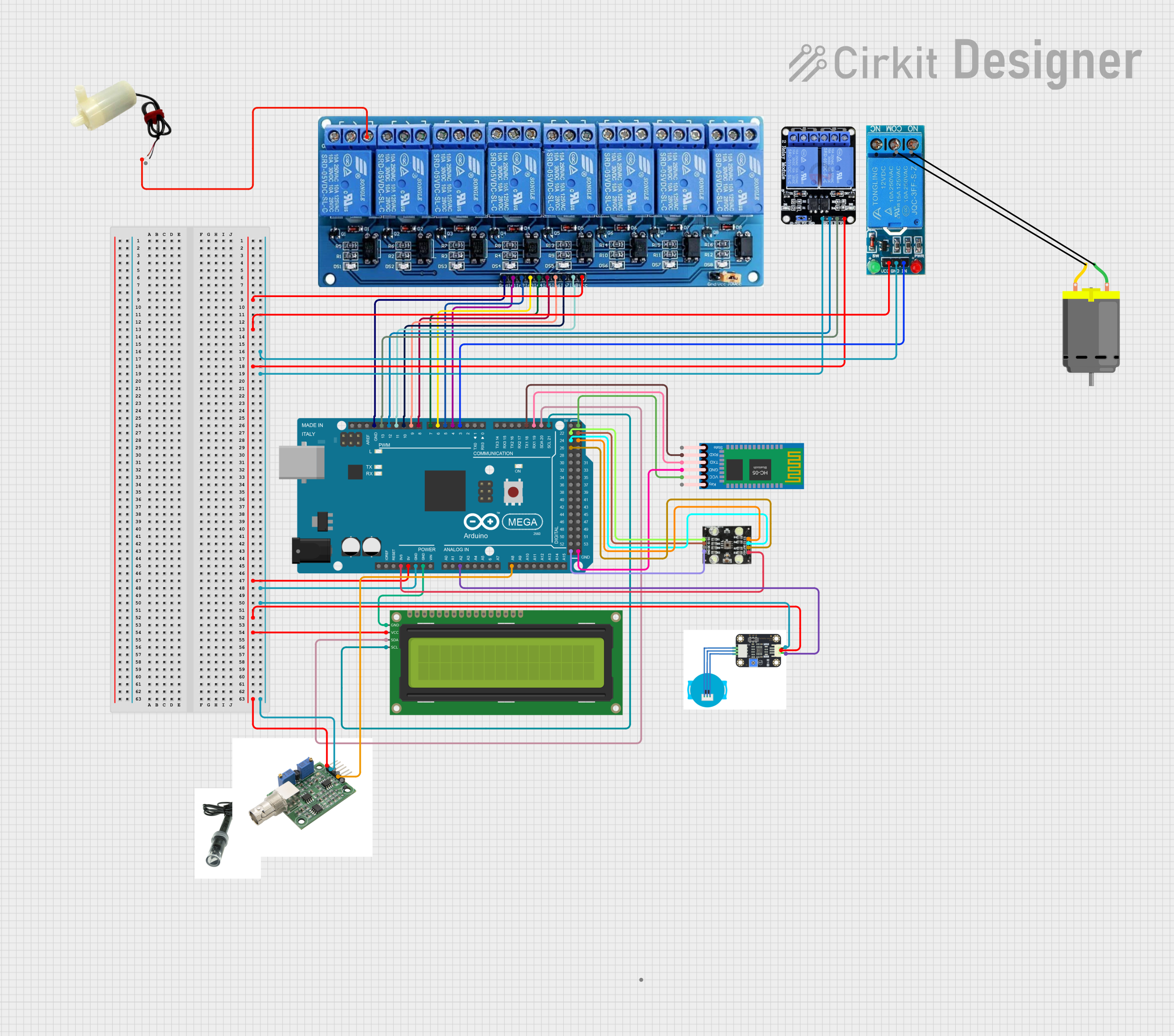
This circuit is an automated chemical testing system controlled by an Arduino Mega 2560. It uses various sensors, including a turbidity sensor and a color sensor, to measure water quality parameters, and it communicates results via an LCD display and Bluetooth module. The system also controls multiple relays to dispense chemicals for different tests.
ESP32-Based RJ45 Cable Tester with LED Indicators and Buzzer
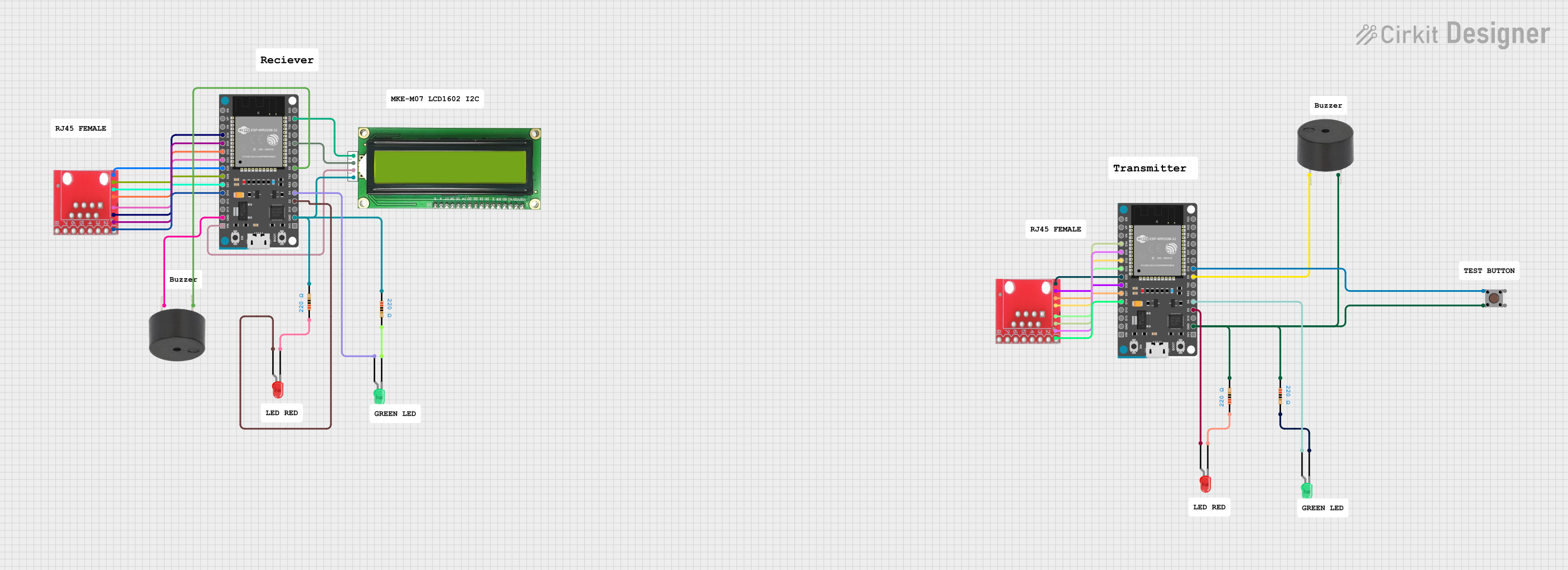
This circuit is a cable tester using two ESP32 microcontrollers to check the continuity and measure the length of RJ45 cables. It includes LEDs, a buzzer, and an LCD for visual and auditory feedback, and a pushbutton to initiate the test. The microcontrollers control the LEDs, buzzer, and LCD, and read the state of the RJ45 pins to determine connectivity and cable length.
Arduino UNO-Based Automated Testing System with Relays and Sensors
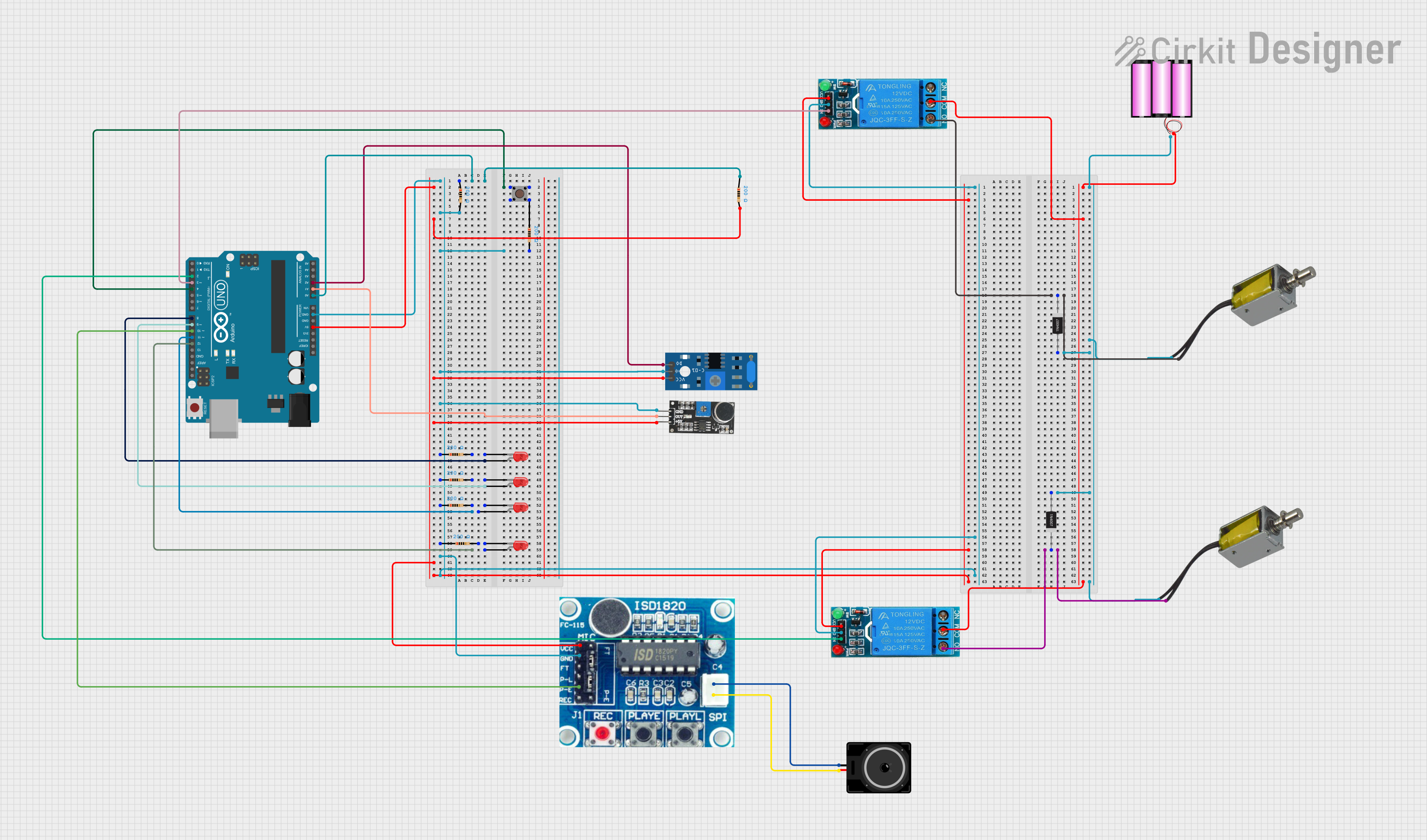
This circuit is an automated testing system controlled by an Arduino UNO, which performs light, vibration, loopback, and melody tests using various sensors and LEDs. The results of these tests are indicated by LEDs and solenoids, with relays controlling the solenoids to signify pass or fail outcomes. The system also includes a sound playback module and a pushbutton to initiate the tests.
Arduino UNO Quiz Game with 16x2 I2C LCD and Pushbuttons
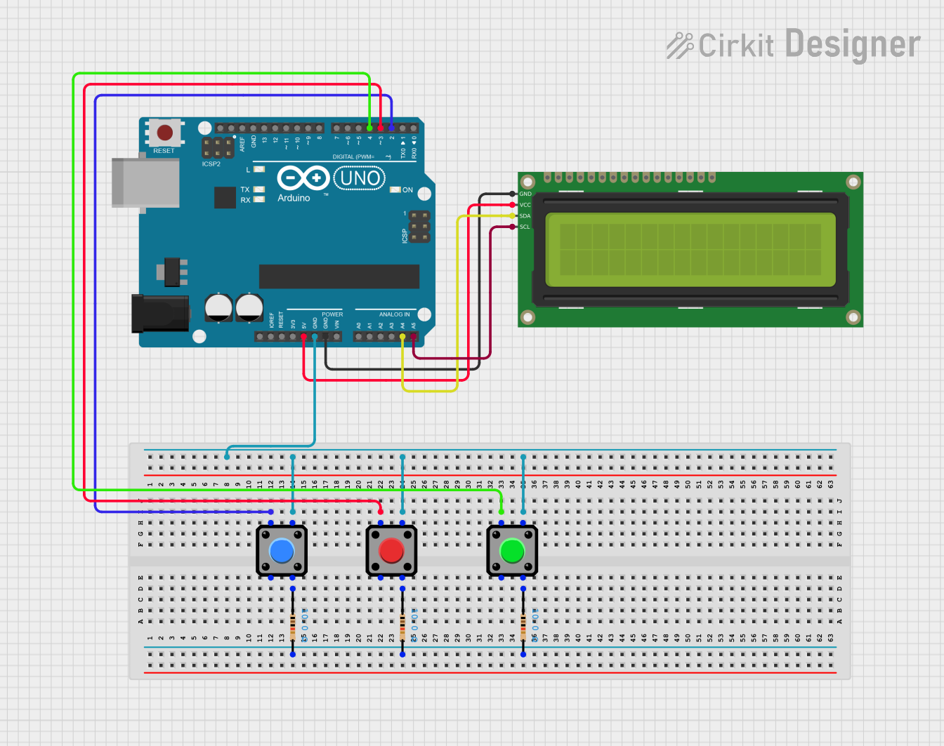
This circuit is a quiz game system using an Arduino UNO, a 16x2 I2C LCD, and three pushbuttons. The Arduino controls the LCD to display questions and receives user input through the buttons to check answers and track the score.
Explore Projects Built with test
Arduino Mega 2560-Based Soil Nutrient Testing System with Bluetooth and LCD Display
This circuit is an automated chemical testing system controlled by an Arduino Mega 2560. It uses various sensors, including a turbidity sensor and a color sensor, to measure water quality parameters, and it communicates results via an LCD display and Bluetooth module. The system also controls multiple relays to dispense chemicals for different tests.
ESP32-Based RJ45 Cable Tester with LED Indicators and Buzzer
This circuit is a cable tester using two ESP32 microcontrollers to check the continuity and measure the length of RJ45 cables. It includes LEDs, a buzzer, and an LCD for visual and auditory feedback, and a pushbutton to initiate the test. The microcontrollers control the LEDs, buzzer, and LCD, and read the state of the RJ45 pins to determine connectivity and cable length.
Arduino UNO-Based Automated Testing System with Relays and Sensors
This circuit is an automated testing system controlled by an Arduino UNO, which performs light, vibration, loopback, and melody tests using various sensors and LEDs. The results of these tests are indicated by LEDs and solenoids, with relays controlling the solenoids to signify pass or fail outcomes. The system also includes a sound playback module and a pushbutton to initiate the tests.
Arduino UNO Quiz Game with 16x2 I2C LCD and Pushbuttons
This circuit is a quiz game system using an Arduino UNO, a 16x2 I2C LCD, and three pushbuttons. The Arduino controls the LCD to display questions and receives user input through the buttons to check answers and track the score.
Technical Specifications
- Key Technical Details:
- Manufacturer: 1
- Voltage Rating: 0–5V (typical, depending on the test scenario)
- Current Rating: 0–100mA (varies based on the circuit being tested)
- Power Dissipation: Up to 0.5W
- Operating Temperature: -40°C to 85°C
- Package Type: Varies (e.g., DIP, SMD, or breadboard-compatible)
Pin Configuration and Descriptions
The pin configuration of the Test Component may vary depending on its specific design. Below is an example of a generic 4-pin test component:
| Pin Number | Pin Name | Description |
|---|---|---|
| 1 | VCC | Power supply input (typically 3.3V or 5V) |
| 2 | GND | Ground connection |
| 3 | IN | Input signal for testing |
| 4 | OUT | Output signal for monitoring |
Usage Instructions
How to use the component in a circuit:
- Connect the VCC pin to the power supply (e.g., 3.3V or 5V, depending on the circuit requirements).
- Connect the GND pin to the ground of the circuit.
- Use the IN pin to input the signal or condition you want to test.
- Monitor the output from the OUT pin to observe the behavior of the circuit under test.
Important considerations and best practices:
- Ensure the voltage and current ratings of the Test Component are not exceeded to avoid damage.
- Use appropriate decoupling capacitors near the power supply pins to minimize noise.
- If using the component with an Arduino UNO or similar microcontroller, ensure proper pin mapping and signal levels.
Example Arduino UNO Code:
// Example code to test a circuit using the Test Component
// Connect the Test Component's OUT pin to Arduino pin A0
// and the IN pin to Arduino pin 9.

const int inputPin = 9;  // Pin connected to the IN pin of the Test Component
const int outputPin = A0; // Pin connected to the OUT pin of the Test Component

void setup() {
  pinMode(inputPin, OUTPUT); // Set inputPin as an output
  pinMode(outputPin, INPUT); // Set outputPin as an input
  Serial.begin(9600);        // Initialize serial communication
}

void loop() {
  digitalWrite(inputPin, HIGH); // Send a HIGH signal to the Test Component
  delay(1000);                  // Wait for 1 second
  int outputValue = analogRead(outputPin); // Read the output signal
  Serial.print("Output Value: ");
  Serial.println(outputValue);  // Print the output value to the Serial Monitor
  delay(1000);                  // Wait for 1 second before repeating
}
Troubleshooting and FAQs
Common issues users might face:
- No output signal from the Test Component:
- Ensure the power supply (VCC and GND) is properly connected.
- Verify that the input signal is within the acceptable range.
- Component overheating:
- Check if the voltage or current exceeds the specified ratings.
- Ensure proper ventilation or heat dissipation in the circuit.
- Unstable or noisy output:
- Add decoupling capacitors near the power supply pins.
- Verify that the input signal is stable and free from noise.
- No output signal from the Test Component:
Solutions and tips for troubleshooting:
- Double-check all connections and ensure they match the pin configuration.
- Use a multimeter or oscilloscope to monitor the input and output signals.
- If using with a microcontroller, confirm that the code is correctly configured for the Test Component.
By following this documentation, users can effectively integrate and utilize the Test Component in their circuit designs for simulation, debugging, and validation purposes.