Cirkit Designer Logo
Cirkit Designer
Your all-in-one circuit design IDE
Home / 
Component Documentation

How to Use Connector 5V: Examples, Pinouts, and Specs

Image of Connector 5V
Cirkit Designer LogoDesign with Connector 5V in Cirkit Designer

Introduction

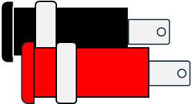
The Connector 5V is an essential electronic component that provides a stable 5-volt power supply to electronic circuits. It is commonly used in a variety of applications, including powering microcontrollers like the Arduino UNO, sensors, and small motors in DIY projects, robotics, and prototyping.

Explore Projects Built with Connector 5V

Use Cirkit Designer to design, explore, and prototype these projects online. Some projects support real-time simulation. Click "Open Project" to start designing instantly!
Dual 5V Power Supply Distribution Circuit with Toggle Switch Control
Image of rfdriver: A project utilizing Connector 5V in a practical application
This circuit consists of two 5V 5A power supplies connected to an AC wall plug point, providing DC output through a 12-way connector. The ground connections from both power supplies are interconnected and also connected to the ground pins of two toggle switches. The DC outputs from the power supplies are separately connected to different pins on the 12-way connector, with each power supply output being switchable via one of the toggle switches.
Cirkit Designer LogoOpen Project in Cirkit Designer
220V to 5V Power Supply with Transformer and Bridge Rectifier
Image of POWER SUPPLY MODULE: A project utilizing Connector 5V in a practical application
This circuit converts 220V AC power to a 5V DC output. It uses a transformer to step down the voltage, a bridge rectifier to convert AC to DC, and a capacitor to smooth the output. The final 5V DC is available through a connector.
Cirkit Designer LogoOpen Project in Cirkit Designer
5-Pin Connector Synchronization Circuit
Image of UMB_Cable: A project utilizing Connector 5V in a practical application
This circuit consists of four 5-pin connectors, where two of the connectors are fully interconnected pin-to-pin. The purpose of this setup could be to create a parallel connection between the two 5-pin connectors, possibly for signal distribution or redundancy.
Cirkit Designer LogoOpen Project in Cirkit Designer
Battery-Powered USB Charger with LED Indicator and DC Motor
Image of Copy of Hand Crank mobile charger : A project utilizing Connector 5V in a practical application
This circuit converts AC power to DC using a bridge rectifier and regulates the voltage to 5V with a 7805 voltage regulator. It powers a USB port and indicates power status with an LED, while also providing a charging interface through a multi-charging cable.
Cirkit Designer LogoOpen Project in Cirkit Designer

Explore Projects Built with Connector 5V

Use Cirkit Designer to design, explore, and prototype these projects online. Some projects support real-time simulation. Click "Open Project" to start designing instantly!
Image of rfdriver: A project utilizing Connector 5V in a practical application
Dual 5V Power Supply Distribution Circuit with Toggle Switch Control
This circuit consists of two 5V 5A power supplies connected to an AC wall plug point, providing DC output through a 12-way connector. The ground connections from both power supplies are interconnected and also connected to the ground pins of two toggle switches. The DC outputs from the power supplies are separately connected to different pins on the 12-way connector, with each power supply output being switchable via one of the toggle switches.
Cirkit Designer LogoOpen Project in Cirkit Designer
Image of POWER SUPPLY MODULE: A project utilizing Connector 5V in a practical application
220V to 5V Power Supply with Transformer and Bridge Rectifier
This circuit converts 220V AC power to a 5V DC output. It uses a transformer to step down the voltage, a bridge rectifier to convert AC to DC, and a capacitor to smooth the output. The final 5V DC is available through a connector.
Cirkit Designer LogoOpen Project in Cirkit Designer
Image of UMB_Cable: A project utilizing Connector 5V in a practical application
5-Pin Connector Synchronization Circuit
This circuit consists of four 5-pin connectors, where two of the connectors are fully interconnected pin-to-pin. The purpose of this setup could be to create a parallel connection between the two 5-pin connectors, possibly for signal distribution or redundancy.
Cirkit Designer LogoOpen Project in Cirkit Designer
Image of Copy of Hand Crank mobile charger : A project utilizing Connector 5V in a practical application
Battery-Powered USB Charger with LED Indicator and DC Motor
This circuit converts AC power to DC using a bridge rectifier and regulates the voltage to 5V with a 7805 voltage regulator. It powers a USB port and indicates power status with an LED, while also providing a charging interface through a multi-charging cable.
Cirkit Designer LogoOpen Project in Cirkit Designer

Technical Specifications

General Specifications

  • Nominal Output Voltage: 5V DC
  • Maximum Output Current: Depending on the model, can range from 500mA to several Amperes
  • Operating Temperature: -20°C to +60°C (typical range)

Pin Configuration and Descriptions

Pin Number Description Notes
1 Vout (+5V) Output pin providing 5V
2 Ground (GND) Reference and return path for current

Note: The actual pin configuration may vary based on the connector type (e.g., barrel jack, USB, etc.). Always refer to the manufacturer's datasheet for exact details.

Usage Instructions

Connecting the Connector 5V to a Circuit

  1. Identify the polarity: Ensure you know which pin is positive (typically marked with a "+") and which is ground.
  2. Voltage verification: Before connecting, use a multimeter to verify the output voltage is 5V.
  3. Load calculation: Ensure the total current draw of your circuit does not exceed the maximum current rating of the connector.
  4. Connection: Connect the positive pin to the Vcc or 5V input on your circuit and the ground pin to the common ground.

Best Practices

  • Polarity check: Always double-check the polarity to prevent damage to the circuit.
  • Secure connections: Use proper connectors or soldering to ensure a stable and secure connection.
  • Heat dissipation: If the connector is supplying high current, ensure adequate ventilation or heat sinks to prevent overheating.
  • Cable management: Use cable organizers to prevent accidental disconnections or shorts.

Troubleshooting and FAQs

Common Issues

  • Voltage drop: If the voltage at the circuit is lower than 5V, check for loose connections or long wires causing resistance.
  • Overheating: If the connector gets too hot, reduce the load or improve heat dissipation.
  • Intermittent power: Check for any physical damage to the connector or wires that may cause a loose connection.

FAQs

Q: Can I use the Connector 5V with an Arduino UNO? A: Yes, the Connector 5V can be used to power an Arduino UNO through its 5V pin or the VIN pin if the connector has a built-in voltage regulator.

Q: What should I do if the connector is not providing power? A: Verify the input power source, check the connections for continuity, and ensure the connector is not damaged.

Q: Is it possible to connect multiple devices to the Connector 5V? A: Yes, as long as the total current draw does not exceed the connector's maximum current rating.

Example Code for Arduino UNO

// Example code to read a sensor value and power it using Connector 5V

const int sensorPin = A0; // Sensor connected to analog pin A0
int sensorValue = 0;      // Variable to store the sensor value

void setup() {
  Serial.begin(9600);       // Start serial communication at 9600 baud
}

void loop() {
  sensorValue = analogRead(sensorPin); // Read the sensor value
  Serial.println(sensorValue);         // Print the sensor value to the serial monitor
  delay(1000);                         // Wait for 1 second before reading again
}

Note: In this example, the Connector 5V is assumed to power the Arduino UNO, which in turn powers the sensor connected to it. The actual setup may vary based on the specific requirements of your project.

Remember to always consult the datasheet of the specific Connector 5V model you are using for precise information regarding its capabilities and limitations.