How to Use arducopter: Examples, Pinouts, and Specs
Introduction
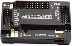
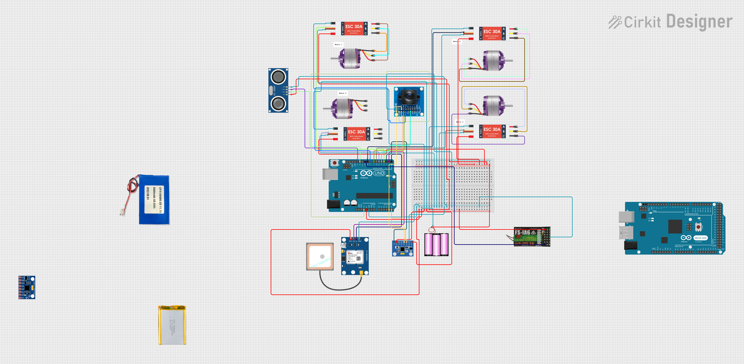
The ArduCopter is a versatile drone platform developed by STM32, designed for aerial robotics applications. It features advanced flight control systems and customizable hardware, making it suitable for a wide range of use cases. Whether you're a hobbyist, researcher, or professional, the ArduCopter provides a reliable and flexible solution for tasks such as aerial photography, surveying, mapping, and autonomous research projects.
Explore Projects Built with arducopter
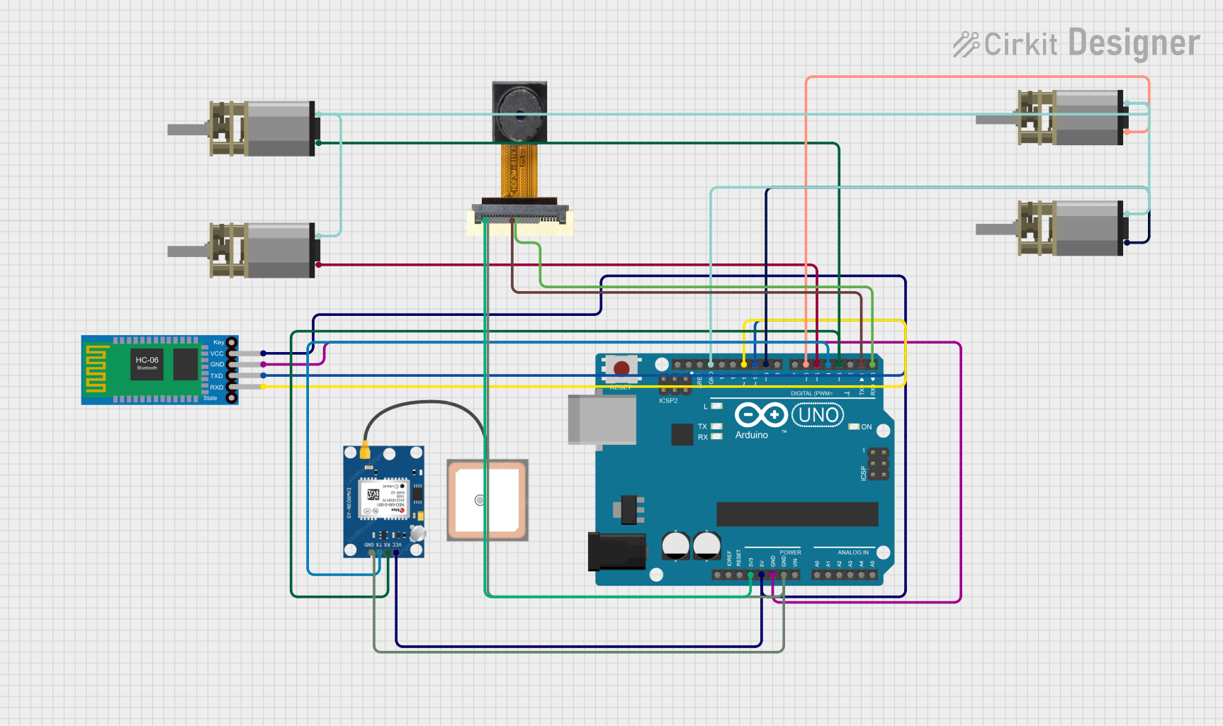
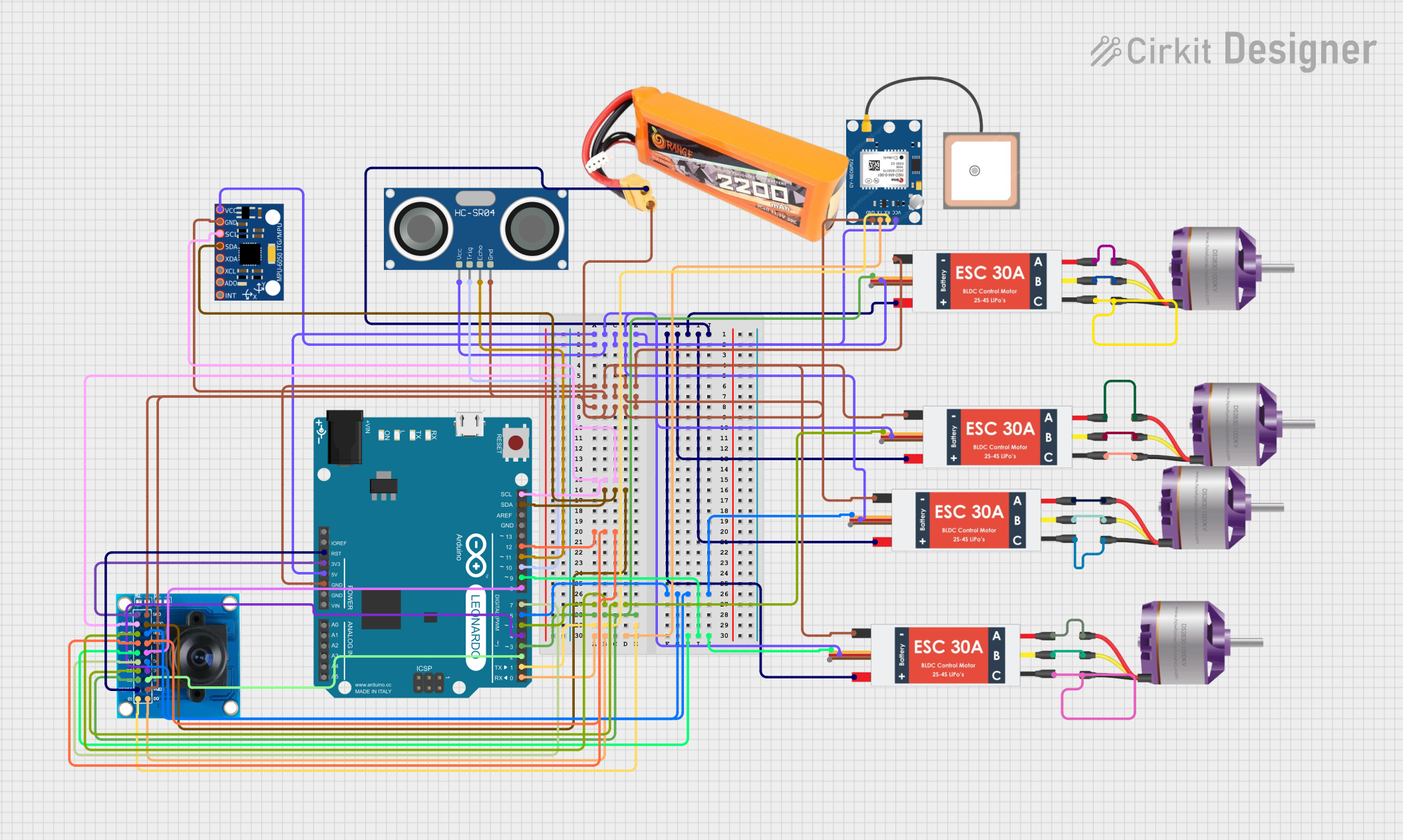
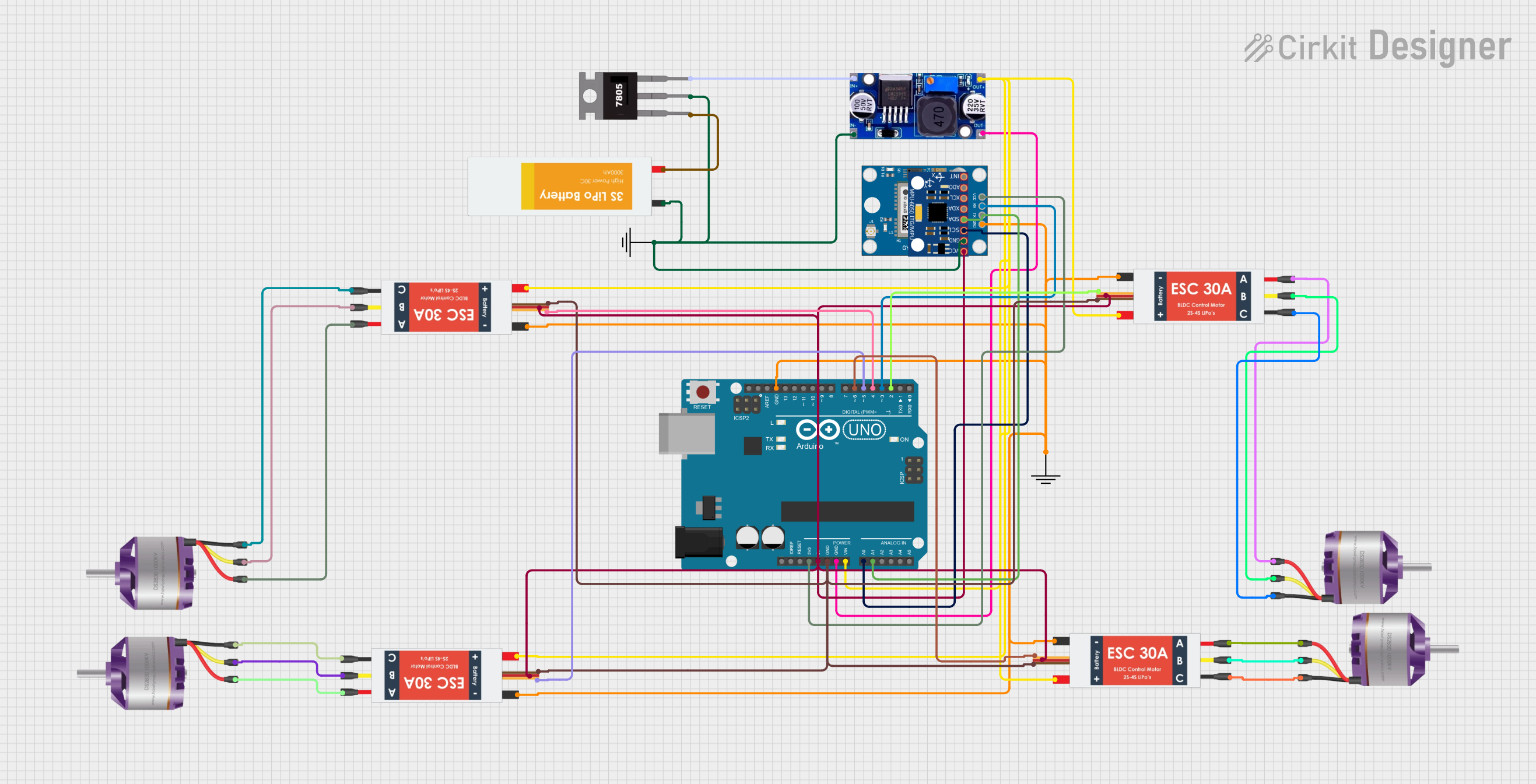
Explore Projects Built with arducopter
Common Applications
- Aerial photography and videography
- Agricultural surveying and crop monitoring
- Search and rescue operations
- Environmental research and mapping
- Autonomous drone research and development
Technical Specifications
Key Technical Details
| Specification | Value |
|---|---|
| Manufacturer | STM32 |
| Manufacturer Part ID | STM32 |
| Processor | STM32 microcontroller (32-bit ARM Cortex) |
| Input Voltage Range | 4.5V to 36V |
| Maximum Current Draw | 90A (depending on motor configuration) |
| Communication Interfaces | UART, I2C, SPI, CAN, PWM |
| Supported Sensors | GPS, IMU, barometer, magnetometer |
| Flight Modes | Stabilize, AltHold, Loiter, Auto, etc. |
| Dimensions | Varies by frame (customizable) |
| Weight | Varies by configuration |
Pin Configuration and Descriptions
The ArduCopter flight controller includes multiple pins for connecting peripherals, sensors, and power. Below is a general pinout description:
| Pin Name | Description |
|---|---|
| GND | Ground connection for power and peripherals |
| VCC | Power input (regulated 5V or battery input) |
| PWM1-PWM8 | Pulse Width Modulation outputs for motor ESCs |
| UART1, UART2 | Serial communication ports for telemetry or external modules |
| I2C_SCL, I2C_SDA | I2C communication lines for sensors like barometers and magnetometers |
| CAN_H, CAN_L | CAN bus communication for advanced peripherals |
| GPS_TX, GPS_RX | GPS module communication pins |
| ADC1, ADC2 | Analog-to-digital converter inputs for voltage or current sensing |
| SWD_CLK, SWD_IO | Debugging and programming interface |
Usage Instructions
How to Use the ArduCopter in a Circuit
Powering the Flight Controller:
Connect a regulated 5V power supply to the VCC and GND pins. Alternatively, you can use a LiPo battery (4S or 6S) connected through a power distribution board (PDB).Connecting Motors and ESCs:
Attach the ESC signal wires to the PWM output pins (PWM1 to PWM8). Ensure the motor order matches the configuration specified in the ArduCopter documentation.Adding Sensors:
- Connect the GPS module to the GPS_TX and GPS_RX pins.
- Attach I2C-based sensors (e.g., barometer, magnetometer) to the I2C_SCL and I2C_SDA pins.
- For additional sensors, use the ADC or UART pins as required.
Programming the Flight Controller:
Use a USB cable or SWD interface to upload firmware via software like Mission Planner or QGroundControl. Ensure the correct firmware version is selected for your hardware.Calibrating the System:
- Perform accelerometer and compass calibration using the ground control software.
- Configure the flight modes and failsafe settings.
Testing the Setup:
Before flying, test the motor outputs, sensor readings, and communication links to ensure proper functionality.
Important Considerations and Best Practices
- Power Supply: Always use a stable power source to avoid voltage drops that could reset the flight controller.
- Firmware Updates: Regularly update the firmware to access new features and bug fixes.
- Safety First: Test the drone in a controlled environment before attempting autonomous or long-range flights.
- GPS Lock: Ensure a strong GPS signal before switching to GPS-dependent flight modes like Loiter or Auto.
Example Code for Arduino UNO Integration
The ArduCopter can communicate with an Arduino UNO via UART for telemetry or control. Below is an example of how to read telemetry data from the ArduCopter:
#include <SoftwareSerial.h>

// Define RX and TX pins for communication with ArduCopter
SoftwareSerial arduCopterSerial(10, 11); // RX = pin 10, TX = pin 11

void setup() {
  Serial.begin(9600); // Initialize serial monitor
  arduCopterSerial.begin(57600); // Initialize communication with ArduCopter

  Serial.println("ArduCopter Telemetry Reader Initialized");
}

void loop() {
  // Check if data is available from ArduCopter
  if (arduCopterSerial.available()) {
    String telemetryData = "";

    // Read all available data
    while (arduCopterSerial.available()) {
      telemetryData += (char)arduCopterSerial.read();
    }

    // Print telemetry data to the serial monitor
    Serial.println("Telemetry Data: " + telemetryData);
  }

  delay(100); // Small delay to avoid flooding the serial monitor
}
Troubleshooting and FAQs
Common Issues and Solutions
Flight Controller Not Powering On
- Cause: Insufficient or incorrect power supply.
- Solution: Verify the input voltage is within the 4.5V to 36V range. Check connections to the VCC and GND pins.
Motors Not Spinning
- Cause: Incorrect ESC connections or calibration.
- Solution: Ensure ESC signal wires are connected to the correct PWM pins. Calibrate the ESCs using the ground control software.
No GPS Lock
- Cause: Poor satellite visibility or incorrect GPS wiring.
- Solution: Move the drone to an open area with a clear view of the sky. Verify GPS module connections to the GPS_TX and GPS_RX pins.
Unstable Flight
- Cause: Incorrect PID tuning or sensor calibration.
- Solution: Recalibrate the accelerometer and compass. Adjust PID values in the ground control software.
FAQs
Can I use the ArduCopter with other microcontrollers?
Yes, the ArduCopter can communicate with other microcontrollers via UART, I2C, or CAN interfaces.What is the maximum payload capacity?
The payload capacity depends on the frame and motor configuration. Refer to the specific frame documentation for details.How do I update the firmware?
Use Mission Planner or QGroundControl to download and upload the latest firmware to the flight controller.Is the ArduCopter compatible with Raspberry Pi?
Yes, the ArduCopter can interface with a Raspberry Pi for advanced processing tasks like image recognition or AI-based navigation.