How to Use PedalPass: Examples, Pinouts, and Specs
Introduction
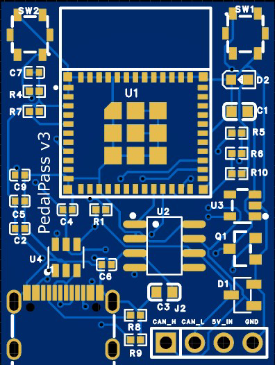
The PedalPass by PedalPass is an electronic circuit component designed for use in audio effects pedals. It enables musicians to seamlessly control the signal path of their instrument by engaging or bypassing the effects circuit with a footswitch. This component is essential for creating dynamic and versatile audio effects setups, allowing for smooth transitions between processed and unprocessed signals during live performances or studio recordings.
Explore Projects Built with PedalPass

Explore Projects Built with PedalPass
Common Applications and Use Cases
- Audio effects pedals for guitars, basses, and other instruments
- Signal routing in pedalboards
- True bypass switching for maintaining signal integrity
- Integration into custom DIY audio effects projects
Technical Specifications
Key Technical Details
| Parameter | Value |
|---|---|
| Operating Voltage | 9V DC (typical for effects pedals) |
| Maximum Current Rating | 50 mA |
| Signal Impedance | 1 MΩ (input), 10 kΩ (output) |
| Switching Type | True Bypass or Buffered Bypass |
| Footswitch Compatibility | SPDT, DPDT, or 3PDT switches |
| PCB Dimensions | 25 mm x 50 mm |
| Mounting Type | Through-hole |
Pin Configuration and Descriptions
| Pin Name | Description |
|---|---|
| IN | Audio signal input from the instrument or previous pedal |
| OUT | Audio signal output to the next pedal or amplifier |
| FX SEND | Sends the signal to the effects circuit |
| FX RETURN | Receives the processed signal from the effects circuit |
| GND | Ground connection |
| V+ | Positive voltage supply (typically 9V DC) |
| SWITCH 1 | Connection to the footswitch for bypass control (SPDT/DPDT/3PDT supported) |
| SWITCH 2 | Additional connection for advanced switching configurations (if applicable) |
Usage Instructions
How to Use the PedalPass in a Circuit
- Power Supply: Connect the V+ pin to a 9V DC power source and the GND pin to the ground.
- Signal Connections:
- Connect the instrument's output to the IN pin.
- Connect the OUT pin to the next pedal in the chain or directly to the amplifier.
- Effects Loop:
- Connect the input of the effects circuit to the FX SEND pin.
- Connect the output of the effects circuit to the FX RETURN pin.
- Footswitch Wiring:
- Use an SPDT, DPDT, or 3PDT footswitch to control the bypass functionality.
- Wire the footswitch to the SWITCH 1 and SWITCH 2 pins as per the desired switching configuration.
Important Considerations and Best Practices
- True Bypass vs. Buffered Bypass: Decide whether you want to implement true bypass (for unaltered signal integrity) or buffered bypass (to prevent signal loss in long cable runs).
- Power Supply Filtering: Use a filtered and regulated 9V DC power supply to avoid introducing noise into the audio signal.
- Footswitch Durability: Ensure the footswitch used is rated for high durability, as it will be subjected to frequent use.
- PCB Mounting: Secure the PedalPass PCB firmly inside the pedal enclosure to prevent damage from vibrations or impacts.
Example Code for Arduino UNO Integration
If you want to control the PedalPass switching electronically using an Arduino UNO, you can use the following example code:
// Example code to control PedalPass switching with an Arduino UNO
// This code assumes a relay or transistor is used to toggle the bypass state

const int switchPin = 7; // Pin connected to the PedalPass SWITCH 1
const int buttonPin = 2; // Pin connected to a momentary push button
int buttonState = 0;     // Variable to store the button state

void setup() {
  pinMode(switchPin, OUTPUT); // Set the switch pin as an output
  pinMode(buttonPin, INPUT_PULLUP); // Set the button pin as an input with pull-up
  digitalWrite(switchPin, LOW); // Initialize the switch in the bypass state
}

void loop() {
  buttonState = digitalRead(buttonPin); // Read the button state

  if (buttonState == LOW) { // Check if the button is pressed
    digitalWrite(switchPin, HIGH); // Engage the effects circuit
    delay(500); // Debounce delay
  } else {
    digitalWrite(switchPin, LOW); // Bypass the effects circuit
  }
}
Note: This example assumes the use of a relay or transistor to toggle the bypass state. Adjust the circuit and code as needed for your specific application.
Troubleshooting and FAQs
Common Issues and Solutions
No Signal Output:
- Verify all connections, especially the IN, OUT, FX SEND, and FX RETURN pins.
- Ensure the footswitch is wired correctly and functioning properly.
- Check the power supply voltage and polarity.
Excessive Noise or Hum:
- Use a filtered and regulated power supply to minimize noise.
- Ensure proper grounding of the circuit and enclosure.
- Check for loose connections or poor solder joints.
Footswitch Not Responding:
- Test the footswitch for continuity using a multimeter.
- Ensure the SWITCH 1 and SWITCH 2 pins are correctly wired.
Signal Loss in Bypass Mode:
- If using true bypass, ensure the footswitch is properly switching the signal path.
- For buffered bypass, verify the buffer circuit is functioning correctly.
FAQs
Q: Can I use the PedalPass with a 12V power supply?
A: The PedalPass is designed for 9V DC operation. Using a 12V supply may damage the component or connected circuits. Always use a 9V regulated power supply.
Q: What type of footswitch is recommended?
A: A 3PDT footswitch is commonly used for true bypass configurations, as it allows for LED indicator control in addition to signal switching.
Q: Can I use the PedalPass for stereo signals?
A: The PedalPass is designed for mono audio signals. For stereo applications, you would need two PedalPass units or a custom stereo switching circuit.
Q: Is the PedalPass compatible with digital effects circuits?
A: Yes, the PedalPass can be used with both analog and digital effects circuits, provided the signal levels and impedance are compatible.