How to Use Sumo Robot Controller R1.1: Examples, Pinouts, and Specs
Introduction
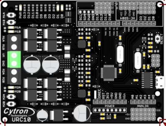
The Sumo Robot Controller R1.1 by Cytron (Part ID: Sumo Robot) is a microcontroller-based control board specifically designed for Sumo robots. It integrates motor drivers, sensor inputs, and programmable logic to enable autonomous navigation and control in Sumo robot competitions. This controller simplifies the process of building and programming Sumo robots, making it ideal for both beginners and experienced robotics enthusiasts.
Explore Projects Built with Sumo Robot Controller R1.1


Explore Projects Built with Sumo Robot Controller R1.1
Common Applications and Use Cases
- Autonomous Sumo robot competitions
- Educational robotics projects
- Prototyping small autonomous vehicles
- Robotics research and development
Technical Specifications
The Sumo Robot Controller R1.1 is equipped with robust features to handle the demands of Sumo robot competitions. Below are the key technical details:
Key Technical Details
| Parameter | Specification |
|---|---|
| Microcontroller | PIC16F877A |
| Operating Voltage | 7V - 12V DC |
| Motor Driver | Dual-channel H-Bridge (2A per channel) |
| Sensor Inputs | 6 analog inputs (e.g., IR sensors) |
| Output Channels | 2 motor outputs (PWM control) |
| Communication Interface | UART (for programming/debugging) |
| Dimensions | 100mm x 80mm |
| Weight | 120g |
Pin Configuration and Descriptions
The Sumo Robot Controller R1.1 features a variety of pins for connecting sensors, motors, and other peripherals. Below is the pin configuration:
Motor Output Pins
| Pin Name | Description |
|---|---|
| M1+ | Motor 1 positive terminal |
| M1- | Motor 1 negative terminal |
| M2+ | Motor 2 positive terminal |
| M2- | Motor 2 negative terminal |
Sensor Input Pins
| Pin Name | Description |
|---|---|
| S1 | Analog input for Sensor 1 |
| S2 | Analog input for Sensor 2 |
| S3 | Analog input for Sensor 3 |
| S4 | Analog input for Sensor 4 |
| S5 | Analog input for Sensor 5 |
| S6 | Analog input for Sensor 6 |
Power and Communication Pins
| Pin Name | Description |
|---|---|
| VIN | Power input (7V - 12V DC) |
| GND | Ground |
| TX | UART transmit |
| RX | UART receive |
Usage Instructions
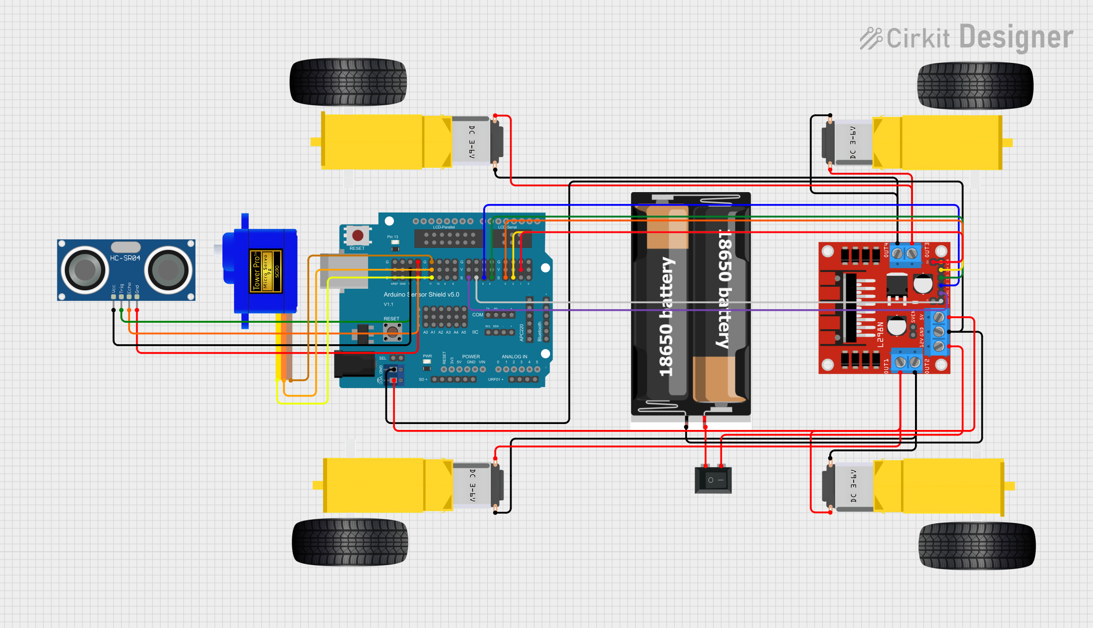
How to Use the Component in a Circuit
- Powering the Board: Connect a DC power supply (7V - 12V) to the VIN and GND pins.
- Connecting Motors: Attach the motors to the M1+/M1- and M2+/M2- terminals. Ensure the motors are within the 2A per channel limit.
- Connecting Sensors: Connect up to six analog sensors (e.g., IR sensors) to the S1-S6 pins. Ensure proper orientation and voltage compatibility.
- Programming the Controller: Use a UART interface to upload code to the microcontroller. A USB-to-UART adapter may be required.
- Testing the Setup: Verify all connections and test the system using simple code to ensure proper operation.
Important Considerations and Best Practices
- Power Supply: Use a stable power source to avoid voltage fluctuations that may affect performance.
- Motor Ratings: Ensure the motors do not exceed the 2A current limit per channel.
- Sensor Placement: Position sensors strategically for optimal performance in Sumo competitions.
- Heat Management: The motor driver may heat up during operation. Ensure adequate ventilation or consider adding a heatsink if necessary.
Example Code for Arduino UNO
The Sumo Robot Controller R1.1 can be interfaced with an Arduino UNO for additional functionality. Below is an example code snippet to control the motors and read sensor values:
// Example code to control motors and read sensors on the Sumo Robot Controller R1.1

// Define motor control pins
#define MOTOR1_PWM 9  // PWM pin for Motor 1
#define MOTOR2_PWM 10 // PWM pin for Motor 2
#define MOTOR1_DIR 8  // Direction pin for Motor 1
#define MOTOR2_DIR 7  // Direction pin for Motor 2

// Define sensor input pins
#define SENSOR1 A0
#define SENSOR2 A1
#define SENSOR3 A2
#define SENSOR4 A3
#define SENSOR5 A4
#define SENSOR6 A5

void setup() {
  // Initialize motor control pins
  pinMode(MOTOR1_PWM, OUTPUT);
  pinMode(MOTOR2_PWM, OUTPUT);
  pinMode(MOTOR1_DIR, OUTPUT);
  pinMode(MOTOR2_DIR, OUTPUT);

  // Initialize sensor pins
  pinMode(SENSOR1, INPUT);
  pinMode(SENSOR2, INPUT);
  pinMode(SENSOR3, INPUT);
  pinMode(SENSOR4, INPUT);
  pinMode(SENSOR5, INPUT);
  pinMode(SENSOR6, INPUT);

  // Start serial communication for debugging
  Serial.begin(9600);
}

void loop() {
  // Example: Read sensor values
  int sensor1Value = analogRead(SENSOR1);
  int sensor2Value = analogRead(SENSOR2);

  // Print sensor values to the Serial Monitor
  Serial.print("Sensor 1: ");
  Serial.println(sensor1Value);
  Serial.print("Sensor 2: ");
  Serial.println(sensor2Value);

  // Example: Control motors
  digitalWrite(MOTOR1_DIR, HIGH); // Set Motor 1 direction
  analogWrite(MOTOR1_PWM, 128);  // Set Motor 1 speed (50%)

  digitalWrite(MOTOR2_DIR, LOW); // Set Motor 2 direction
  analogWrite(MOTOR2_PWM, 200); // Set Motor 2 speed (78%)

  delay(1000); // Wait for 1 second
}
Troubleshooting and FAQs
Common Issues and Solutions
Motors Not Running:
- Cause: Incorrect wiring or insufficient power supply.
- Solution: Verify motor connections and ensure the power supply meets the voltage and current requirements.
Sensors Not Responding:
- Cause: Faulty sensor connections or incompatible sensors.
- Solution: Check sensor wiring and ensure the sensors are analog and within the voltage range.
Overheating Motor Driver:
- Cause: Motors drawing excessive current.
- Solution: Use motors within the 2A per channel limit and ensure proper ventilation.
Microcontroller Not Responding:
- Cause: Incorrect programming or communication settings.
- Solution: Verify UART connections and ensure the correct baud rate is used.
FAQs
Can I use digital sensors with this controller?
- Yes, but you will need to use additional circuitry to convert digital signals to analog if required.
What is the maximum robot weight this controller can handle?
- The weight depends on the motors used. Ensure the motors are compatible with the controller's current limits.
Can I use this controller with a LiPo battery?
- Yes, as long as the battery voltage is within the 7V - 12V range.
Is the controller compatible with Arduino IDE?
- The controller itself is not programmable via Arduino IDE, but it can interface with an Arduino board for extended functionality.