Cirkit Designer Logo
Cirkit Designer
Your all-in-one circuit design IDE
Home / 
Component Documentation

How to Use SparkFun ESP8266 Thing - Dev Board: Examples, Pinouts, and Specs

Image of SparkFun ESP8266 Thing - Dev Board
Cirkit Designer LogoDesign with SparkFun ESP8266 Thing - Dev Board in Cirkit Designer

Introduction

The SparkFun ESP8266 Thing - Dev Board is a comprehensive development platform for the ESP8266, which is a highly integrated Wi-Fi SoC (System on Chip) that offers a self-contained networking solution. It enables users to add robust and versatile Wi-Fi capabilities to their projects with minimal hassle. Common applications include Internet of Things (IoT) devices, home automation, sensor networks, and Wi-Fi enabled prototypes.

Explore Projects Built with SparkFun ESP8266 Thing - Dev Board

Use Cirkit Designer to design, explore, and prototype these projects online. Some projects support real-time simulation. Click "Open Project" to start designing instantly!
Wi-Fi Controlled Battery-Powered Dual Motor Driver with ESP8266
Image of IOT: A project utilizing SparkFun ESP8266 Thing - Dev Board in a practical application
This circuit uses a SparkFun ESP8266 Thing Dev Board to control two DC motors via an L298N motor driver. The ESP8266 receives power from a 4 x AAA battery mount and sends control signals to the motor driver, which in turn drives the motors.
Cirkit Designer LogoOpen Project in Cirkit Designer
ESP32-Based GPS Tracker with SD Card Logging and Barometric Sensor
Image of gps projekt circuit: A project utilizing SparkFun ESP8266 Thing - Dev Board in a practical application
This circuit features an ESP32 Wroom Dev Kit as the main microcontroller, interfaced with an MPL3115A2 sensor for pressure and temperature readings, and a Neo 6M GPS module for location tracking. The ESP32 is also connected to an SD card reader for data logging purposes. A voltage regulator is used to step down the USB power supply to 3.3V, which powers the ESP32, the sensor, and the SD card reader.
Cirkit Designer LogoOpen Project in Cirkit Designer
ESP8266 WiFi Module Serial Interface with Pushbutton Control
Image of esp01 progrmmer: A project utilizing SparkFun ESP8266 Thing - Dev Board in a practical application
This circuit features an ESP8266 ESP-01 WiFi module interfaced with an Adafruit FTDI Friend for serial communication. The ESP8266's TXD and RXD pins are connected to the FTDI's RX and TX pins respectively, allowing for data exchange between the microcontroller and a computer. Additionally, a pushbutton is connected to the ESP8266's reset pin, enabling manual resets of the module.
Cirkit Designer LogoOpen Project in Cirkit Designer
ESP32-Based Environmental Monitoring and Alert System with Solar Charging
Image of mark: A project utilizing SparkFun ESP8266 Thing - Dev Board in a practical application
This circuit features an ESP32 Devkit V1 microcontroller connected to various sensors and modules for monitoring and communication purposes. It includes an MQ-2 gas sensor and a DHT11 temperature and humidity sensor, both interfaced with the ESP32 for environmental data collection. The circuit is powered by a 12V battery, regulated to 5V by step-down converters, and includes a solar charge controller connected to a solar panel for battery charging, a UPS module for power management, and a SIM900A module for GSM communication. Additionally, there is a WS2812 RGB LED strip for visual feedback and a piezo buzzer for audio alerts, both controlled by the ESP32.
Cirkit Designer LogoOpen Project in Cirkit Designer

Explore Projects Built with SparkFun ESP8266 Thing - Dev Board

Use Cirkit Designer to design, explore, and prototype these projects online. Some projects support real-time simulation. Click "Open Project" to start designing instantly!
Image of IOT: A project utilizing SparkFun ESP8266 Thing - Dev Board in a practical application
Wi-Fi Controlled Battery-Powered Dual Motor Driver with ESP8266
This circuit uses a SparkFun ESP8266 Thing Dev Board to control two DC motors via an L298N motor driver. The ESP8266 receives power from a 4 x AAA battery mount and sends control signals to the motor driver, which in turn drives the motors.
Cirkit Designer LogoOpen Project in Cirkit Designer
Image of gps projekt circuit: A project utilizing SparkFun ESP8266 Thing - Dev Board in a practical application
ESP32-Based GPS Tracker with SD Card Logging and Barometric Sensor
This circuit features an ESP32 Wroom Dev Kit as the main microcontroller, interfaced with an MPL3115A2 sensor for pressure and temperature readings, and a Neo 6M GPS module for location tracking. The ESP32 is also connected to an SD card reader for data logging purposes. A voltage regulator is used to step down the USB power supply to 3.3V, which powers the ESP32, the sensor, and the SD card reader.
Cirkit Designer LogoOpen Project in Cirkit Designer
Image of esp01 progrmmer: A project utilizing SparkFun ESP8266 Thing - Dev Board in a practical application
ESP8266 WiFi Module Serial Interface with Pushbutton Control
This circuit features an ESP8266 ESP-01 WiFi module interfaced with an Adafruit FTDI Friend for serial communication. The ESP8266's TXD and RXD pins are connected to the FTDI's RX and TX pins respectively, allowing for data exchange between the microcontroller and a computer. Additionally, a pushbutton is connected to the ESP8266's reset pin, enabling manual resets of the module.
Cirkit Designer LogoOpen Project in Cirkit Designer
Image of mark: A project utilizing SparkFun ESP8266 Thing - Dev Board in a practical application
ESP32-Based Environmental Monitoring and Alert System with Solar Charging
This circuit features an ESP32 Devkit V1 microcontroller connected to various sensors and modules for monitoring and communication purposes. It includes an MQ-2 gas sensor and a DHT11 temperature and humidity sensor, both interfaced with the ESP32 for environmental data collection. The circuit is powered by a 12V battery, regulated to 5V by step-down converters, and includes a solar charge controller connected to a solar panel for battery charging, a UPS module for power management, and a SIM900A module for GSM communication. Additionally, there is a WS2812 RGB LED strip for visual feedback and a piezo buzzer for audio alerts, both controlled by the ESP32.
Cirkit Designer LogoOpen Project in Cirkit Designer

Technical Specifications

Key Technical Details

  • Wi-Fi Module: ESP8266
  • Operating Voltage: 3.3V
  • Input Voltage (recommended): 4-6V (via LiPo battery or USB)
  • Input Voltage (limits): 3.3-6V
  • Digital I/O Pins: 11
  • Analog Input Pins: 1 (Max input: 1V)
  • Flash Memory: 512KB (upgradable to 1MB)
  • SRAM: 80KB
  • Clock Speed: 80MHz (upgradable to 160MHz)
  • Wi-Fi Standards: 802.11 b/g/n
  • Integrated TCP/IP protocol stack

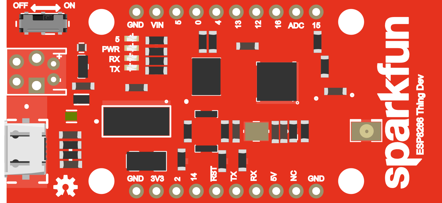
Pin Configuration and Descriptions

Pin Number Function Description
1 TX UART transmit (connects to RX of USB-to-serial adapter)
2 RX UART receive (connects to TX of USB-to-serial adapter)
3 RST Reset (active low)
4 CH_PD Chip Power-Down (active high)
5 GPIO0 General-purpose I/O and bootstrapping pin
6 GPIO2 General-purpose I/O
7 GPIO4 General-purpose I/O
8 GPIO5 General-purpose I/O
9 GPIO12 General-purpose I/O
10 GPIO13 General-purpose I/O
11 GPIO14 General-purpose I/O
12 GPIO15 General-purpose I/O
13 GPIO16 General-purpose I/O, deep sleep wake-up
14 A0 Analog input
15 SDA I2C data line
16 SCL I2C clock line
17 VCC 3.3V power supply input
18 GND Ground

Usage Instructions

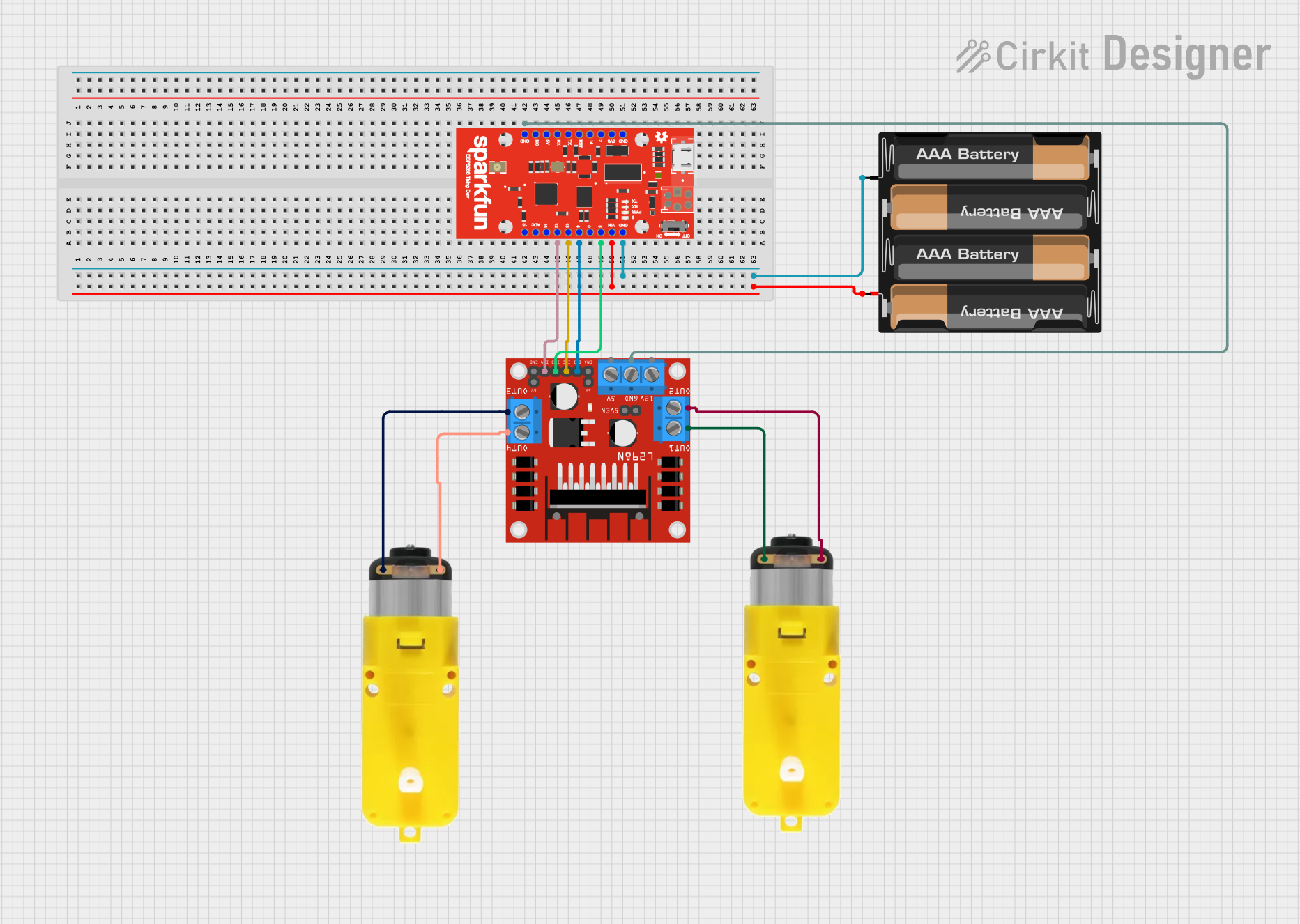
How to Use the Component in a Circuit

  1. Powering the Board:

    • Connect a LiPo battery to the JST connector for mobile applications.
    • Alternatively, power the board via the micro USB connector.
  2. Programming the Board:

    • Install the necessary drivers and the Arduino IDE.
    • Select the appropriate board from the Tools > Board menu.
    • Choose the correct port from Tools > Port.
  3. Connecting to Wi-Fi:

    • Use the ESP8266WiFi library included with the Arduino IDE.
    • Utilize the WiFi.begin(ssid, password) function to connect to a network.
  4. Interfacing with Sensors and Actuators:

    • Connect sensors to the analog or digital pins as required.
    • Ensure that the voltage levels are compatible (3.3V logic).

Important Considerations and Best Practices

  • Always ensure that the power supply is within the specified limits to prevent damage.
  • Use a logic level converter if interfacing with 5V components.
  • Avoid drawing too much current from the I/O pins to prevent damage (max 12mA per pin).
  • When programming, ensure GPIO0 is grounded to enable the bootloader mode.

Troubleshooting and FAQs

Common Issues

  • Board not connecting to Wi-Fi:

    • Check the SSID and password.
    • Ensure the board is within range of the router.
    • Verify that the Wi-Fi network is 2.4GHz (ESP8266 does not support 5GHz).
  • Board not recognized by the computer:

    • Install the correct USB-to-serial drivers.
    • Try a different USB cable or port.
  • Unable to program the board:

    • Ensure GPIO0 is grounded during boot to enable flash mode.
    • Check the board and port settings in the Arduino IDE.

Solutions and Tips for Troubleshooting

  • Use serial print statements to debug and track program flow.
  • Check power and ground connections if the board behaves erratically.
  • Update the firmware of the ESP8266 if facing issues with Wi-Fi connectivity.

Example Code for Arduino UNO

#include <ESP8266WiFi.h>

const char* ssid = "yourSSID";
const char* password = "yourPASSWORD";

void setup() {
  Serial.begin(115200);
  // Connect to Wi-Fi
  WiFi.begin(ssid, password);
  while (WiFi.status() != WL_CONNECTED) {
    delay(500);
    Serial.print(".");
  }
  Serial.println("");
  Serial.print("Connected to ");
  Serial.println(ssid);
  Serial.print("IP address: ");
  Serial.println(WiFi.localIP());
}

void loop() {
  // Your code here
}

Remember to replace yourSSID and yourPASSWORD with your actual Wi-Fi network's SSID and password. This code initializes the Wi-Fi connection and, once connected, prints the local IP address to the serial monitor.