Cirkit Designer Logo
Cirkit Designer
Your all-in-one circuit design IDE
Home / 
Component Documentation

How to Use SparkFun IR Array Breakout - 110 Degree FOV, MLX90640 (Qwiic): Examples, Pinouts, and Specs

Image of SparkFun IR Array Breakout - 110 Degree FOV, MLX90640 (Qwiic)
Cirkit Designer LogoDesign with SparkFun IR Array Breakout - 110 Degree FOV, MLX90640 (Qwiic) in Cirkit Designer

Introduction

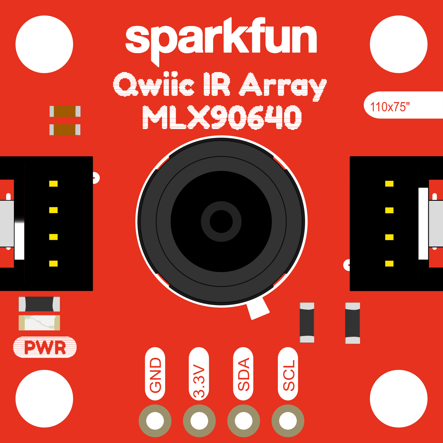
The SparkFun IR Array Breakout is a sophisticated sensor module designed to capture thermal images using infrared (IR) radiation. It utilizes the MLX90640 sensor to provide a thermal imaging solution with a 110-degree field of view (FOV). This breakout board simplifies the integration of the sensor with various microcontroller platforms, especially those compatible with the Qwiic connect system, which allows for easy daisy-chaining and requires no soldering.

Explore Projects Built with SparkFun IR Array Breakout - 110 Degree FOV, MLX90640 (Qwiic)

Use Cirkit Designer to design, explore, and prototype these projects online. Some projects support real-time simulation. Click "Open Project" to start designing instantly!
Arduino Nano-Powered PID Line Following Robot with Reflectance Sensor Array and Dual Motor Driver
Image of Line following bot: A project utilizing SparkFun IR Array Breakout - 110 Degree FOV, MLX90640 (Qwiic) in a practical application
This circuit is designed for an advanced line-following robot that uses a QTRX-HD-07RC Reflectance Sensor Array for line sensing and a Motor Driver 1A Dual TB6612FNG to control two DC Mini Metal Gear Motors. The Arduino Nano serves as the microcontroller, running a PID control algorithm to adjust the motor speeds for precise tracking. Power is supplied by a 5V battery for the logic and a 12V battery for the motor driver.
Cirkit Designer LogoOpen Project in Cirkit Designer
Battery-Powered Smart Sensor Hub with Adafruit QT Py RP2040
Image of wearable final: A project utilizing SparkFun IR Array Breakout - 110 Degree FOV, MLX90640 (Qwiic) in a practical application
This circuit features an Adafruit QT Py RP2040 microcontroller interfaced with an APDS9960 proximity sensor, an MPU6050 accelerometer and gyroscope, and an OLED display via I2C communication. It also includes a buzzer controlled by the microcontroller and is powered by a 3.7V LiPo battery with a toggle switch for power control.
Cirkit Designer LogoOpen Project in Cirkit Designer
Adafruit MPU6050 and VL6180X Sensor Interface with Servo Control
Image of wire: A project utilizing SparkFun IR Array Breakout - 110 Degree FOV, MLX90640 (Qwiic) in a practical application
This circuit features an Adafruit QT Py microcontroller interfaced with an Adafruit MPU6050 6-axis accelerometer/gyroscope and an Adafruit VL6180X Time of Flight (ToF) distance sensor, both connected via I2C communication. The QT Py also controls a Servomotor SG90, likely for physical actuation based on sensor inputs. The embedded code initializes the sensors, reads their data, and outputs the readings to a serial monitor, with the potential for motion control based on the sensor feedback.
Cirkit Designer LogoOpen Project in Cirkit Designer
ESP32-CAM and IR Sensor Interface with USB UART Communication
Image of esp32cam parking: A project utilizing SparkFun IR Array Breakout - 110 Degree FOV, MLX90640 (Qwiic) in a practical application
This circuit features an ESP32 CAM module interfaced with an IR sensor and a SparkFun USB UART Breakout board. The ESP32 CAM provides power to the IR sensor and receives its output signal, likely for processing or triggering camera actions based on IR detection. The USB UART Breakout board is connected to the ESP32 CAM for serial communication, enabling programming, debugging, or data exchange with a computer.
Cirkit Designer LogoOpen Project in Cirkit Designer

Explore Projects Built with SparkFun IR Array Breakout - 110 Degree FOV, MLX90640 (Qwiic)

Use Cirkit Designer to design, explore, and prototype these projects online. Some projects support real-time simulation. Click "Open Project" to start designing instantly!
Image of Line following bot: A project utilizing SparkFun IR Array Breakout - 110 Degree FOV, MLX90640 (Qwiic) in a practical application
Arduino Nano-Powered PID Line Following Robot with Reflectance Sensor Array and Dual Motor Driver
This circuit is designed for an advanced line-following robot that uses a QTRX-HD-07RC Reflectance Sensor Array for line sensing and a Motor Driver 1A Dual TB6612FNG to control two DC Mini Metal Gear Motors. The Arduino Nano serves as the microcontroller, running a PID control algorithm to adjust the motor speeds for precise tracking. Power is supplied by a 5V battery for the logic and a 12V battery for the motor driver.
Cirkit Designer LogoOpen Project in Cirkit Designer
Image of wearable final: A project utilizing SparkFun IR Array Breakout - 110 Degree FOV, MLX90640 (Qwiic) in a practical application
Battery-Powered Smart Sensor Hub with Adafruit QT Py RP2040
This circuit features an Adafruit QT Py RP2040 microcontroller interfaced with an APDS9960 proximity sensor, an MPU6050 accelerometer and gyroscope, and an OLED display via I2C communication. It also includes a buzzer controlled by the microcontroller and is powered by a 3.7V LiPo battery with a toggle switch for power control.
Cirkit Designer LogoOpen Project in Cirkit Designer
Image of wire: A project utilizing SparkFun IR Array Breakout - 110 Degree FOV, MLX90640 (Qwiic) in a practical application
Adafruit MPU6050 and VL6180X Sensor Interface with Servo Control
This circuit features an Adafruit QT Py microcontroller interfaced with an Adafruit MPU6050 6-axis accelerometer/gyroscope and an Adafruit VL6180X Time of Flight (ToF) distance sensor, both connected via I2C communication. The QT Py also controls a Servomotor SG90, likely for physical actuation based on sensor inputs. The embedded code initializes the sensors, reads their data, and outputs the readings to a serial monitor, with the potential for motion control based on the sensor feedback.
Cirkit Designer LogoOpen Project in Cirkit Designer
Image of esp32cam parking: A project utilizing SparkFun IR Array Breakout - 110 Degree FOV, MLX90640 (Qwiic) in a practical application
ESP32-CAM and IR Sensor Interface with USB UART Communication
This circuit features an ESP32 CAM module interfaced with an IR sensor and a SparkFun USB UART Breakout board. The ESP32 CAM provides power to the IR sensor and receives its output signal, likely for processing or triggering camera actions based on IR detection. The USB UART Breakout board is connected to the ESP32 CAM for serial communication, enabling programming, debugging, or data exchange with a computer.
Cirkit Designer LogoOpen Project in Cirkit Designer

Common Applications and Use Cases

  • Human presence detection
  • Temperature measurement across a scene
  • Thermal imaging for security systems
  • Environmental monitoring
  • Energy conservation systems
  • Industrial temperature monitoring of machinery

Technical Specifications

Key Technical Details

  • Sensor: MLX90640
  • Interface: I2C (Qwiic compatible)
  • Field of View (FOV): 110 degrees
  • Resolution: 32x24 pixels
  • Measurement Range: -40°C to 300°C
  • Refresh Rate: 0.5Hz to 64Hz
  • Supply Voltage: 3V to 3.6V
  • Current Consumption: 23mA (typical)

Pin Configuration and Descriptions

Pin Name Description
GND Ground connection
VCC Power supply (3V to 3.6V)
SDA I2C data line
SCL I2C clock line
INT Interrupt pin (optional use)

Usage Instructions

How to Use the Component in a Circuit

  1. Power Connections: Connect the VCC pin to a 3.3V source and the GND pin to the ground on your microcontroller board.
  2. I2C Connections: Connect the SDA and SCL pins to the corresponding I2C data and clock lines on your microcontroller.
  3. Qwiic Connection: If using a Qwiic-enabled board, simply connect the Qwiic cable from the breakout board to the microcontroller's Qwiic connector.

Important Considerations and Best Practices

  • Ensure that the power supply is within the specified voltage range to prevent damage.
  • Use pull-up resistors on the I2C lines if they are not already present on your microcontroller board.
  • Avoid physical obstructions in front of the sensor that could block the IR radiation.
  • For accurate temperature readings, calibrate the sensor for the specific application environment.

Example Code for Arduino UNO

#include <Wire.h>
#include <Adafruit_MLX90640.h>

Adafruit_MLX90640 mlx;

void setup() {
  Serial.begin(9600);
  while (!Serial) delay(10); // wait for serial port to connect

  Serial.println("MLX90640 IR Array Example");

  // Initialize the MLX90640 sensor
  if (!mlx.begin()) {
    Serial.println("Failed to initialize MLX90640!");
    while (1) delay(10);
  }
  // Set the refresh rate to 2Hz
  mlx.setRefreshRate(MLX90640_REFRESH_2_HZ);
}

void loop() {
  float mlx90640Frame[32 * 24]; // buffer for full frame of temperatures

  // Capture an image frame
  if (mlx.getFrame(mlx90640Frame)) {
    for (int i = 0; i < 32 * 24; i++) {
      Serial.print(mlx90640Frame[i]);
      Serial.print(",");
      if ((i + 1) % 32 == 0) {
        Serial.println();
      }
    }
    Serial.println();
  } else {
    Serial.println("Failed to read frame");
  }

  delay(500); // Delay between frames
}

Troubleshooting and FAQs

Common Issues Users Might Face

  • No Data on Serial Monitor: Ensure that the SDA and SCL connections are secure and that the correct I2C address is being used.
  • Inaccurate Temperature Readings: Calibrate the sensor for the environment where it is being used. Also, check for any objects that might be blocking the sensor's FOV.
  • Sensor Not Detected: Verify that the power supply is within the specified range and that the I2C lines are properly connected with pull-up resistors.

Solutions and Tips for Troubleshooting

  • Double-check wiring connections and ensure that the microcontroller is supplying 3.3V to the VCC pin.
  • Use the I2C scanner sketch to confirm that the sensor is detected on the I2C bus.
  • If using long cables for I2C connection, consider using shielded cables to prevent noise.

FAQs

Q: Can the MLX90640 sensor be used outdoors? A: Yes, but it should be protected from direct sunlight and harsh weather conditions to maintain accuracy.

Q: What is the maximum I2C bus length for the sensor? A: It is recommended to keep the I2C bus length as short as possible, ideally less than 1 meter, to ensure reliable communication.

Q: Can the sensor detect through glass or other materials? A: No, the MLX90640 cannot detect IR radiation through glass or similar materials as they block IR wavelengths.

Q: How do I change the I2C address of the sensor? A: The I2C address of the MLX90640 sensor is fixed and cannot be changed. If you need to use multiple sensors, you will need an I2C multiplexer.

Q: Is it possible to change the refresh rate of the sensor? A: Yes, the refresh rate can be adjusted using the mlx.setRefreshRate() function in the provided library.