How to Use Pilot Lamp Red: Examples, Pinouts, and Specs
Introduction
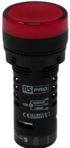
A Pilot Lamp Red is an indicator lamp commonly used in electronic circuits to provide visual feedback about the status of a system or component. The red color is often associated with warnings, errors, or critical states, making it an essential tool for monitoring and diagnostics. These lamps are widely used in control panels, appliances, machinery, and various types of equipment to signal power on/off status, fault conditions, or as a part of user interfaces.
Explore Projects Built with Pilot Lamp Red
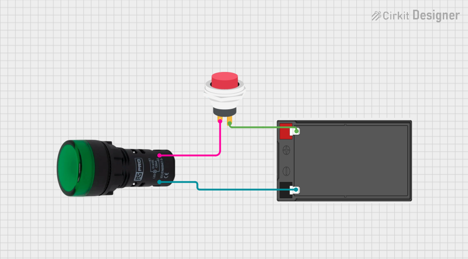
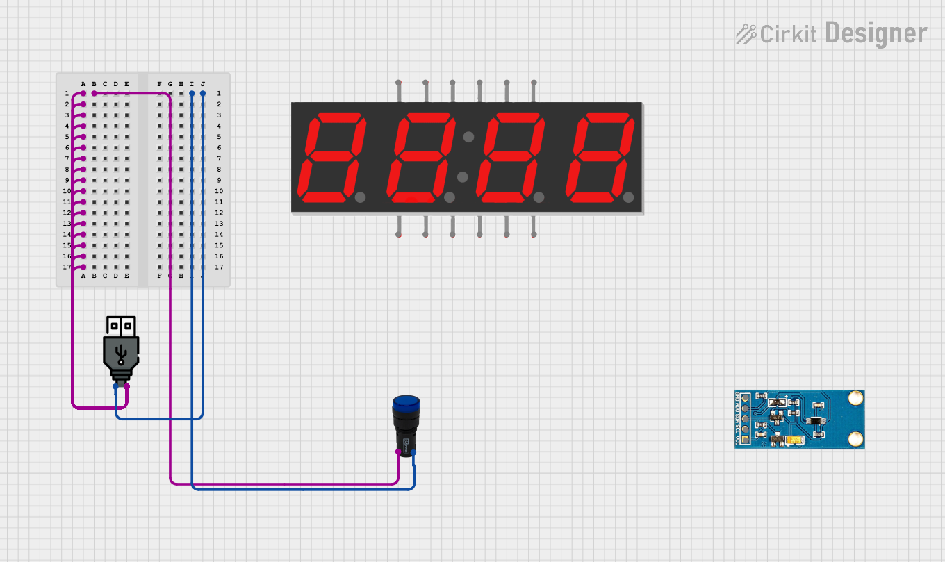
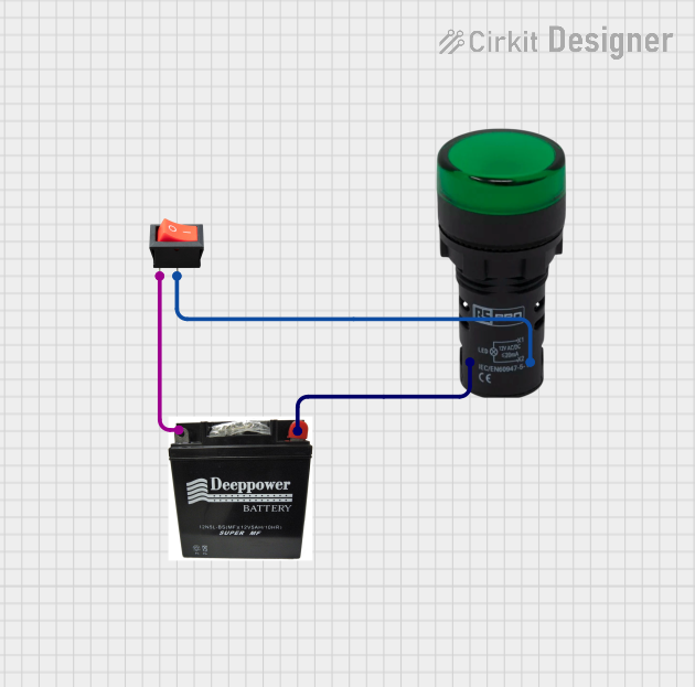
Explore Projects Built with Pilot Lamp Red
Common Applications and Use Cases
- Power status indication on electronic devices
- Alerting users to fault conditions in machinery
- Displaying the active state of a security system
- Signaling the operation of a heating element
Technical Specifications
Key Technical Details
- Rated Voltage: Typically 110V or 220V AC (model-specific)
- Current Consumption: Depends on the lamp's power rating, usually in the range of 10-20 mA
- Power Rating: Generally around 0.2W to 2W
- Lifespan: Approximately 10,000 to 30,000 hours of continuous use
- Operating Temperature: -20°C to +60°C
Pin Configuration and Descriptions
| Pin Number | Description |
|---|---|
| 1 | Live (Phase) Input |
| 2 | Neutral Return Path |
Usage Instructions
How to Use the Pilot Lamp Red in a Circuit
- Power Source: Ensure that the power source matches the rated voltage of the Pilot Lamp Red.
- Wiring: Connect the live (phase) wire to Pin 1 and the neutral wire to Pin 2.
- Mounting: Secure the lamp in the desired location, ensuring it is visible to the operator.
- Testing: Power on the circuit to test the lamp's functionality.
Important Considerations and Best Practices
- Voltage Matching: Always verify that the lamp's voltage rating is compatible with the circuit voltage.
- Heat Dissipation: Ensure adequate spacing around the lamp for heat dissipation.
- Protection: Use a fuse or circuit breaker to protect against overcurrent conditions.
- Visibility: Position the lamp where it can be easily seen by the user.
Troubleshooting and FAQs
Common Issues Users Might Face
- Lamp Does Not Illuminate: Check the power supply and connections. Ensure the voltage matches the lamp's rating.
- Flickering Lamp: This may indicate a loose connection or fluctuating power supply. Secure all connections and check the input voltage stability.
- Burnt Out Lamp: Replace the lamp if it has reached the end of its lifespan or if it has been subjected to overvoltage.
Solutions and Tips for Troubleshooting
- No Light: Verify the power source and connections. Test the lamp with a multimeter to ensure it is not defective.
- Flickering: Tighten connections and consider using a voltage regulator if the power supply is unstable.
- Replacement: When replacing the lamp, ensure the power is off and the lamp has cooled down to avoid injury.
Code Example for Arduino UNO Connection
// Code to blink an external Pilot Lamp Red connected to an Arduino UNO

const int pilotLampPin = 13; // Assign the pin connected to the Pilot Lamp Red

void setup() {
  pinMode(pilotLampPin, OUTPUT); // Set the pilot lamp pin as an output
}

void loop() {
  digitalWrite(pilotLampPin, HIGH); // Turn on the pilot lamp
  delay(1000);                      // Wait for 1 second
  digitalWrite(pilotLampPin, LOW);  // Turn off the pilot lamp
  delay(1000);                      // Wait for 1 second
}
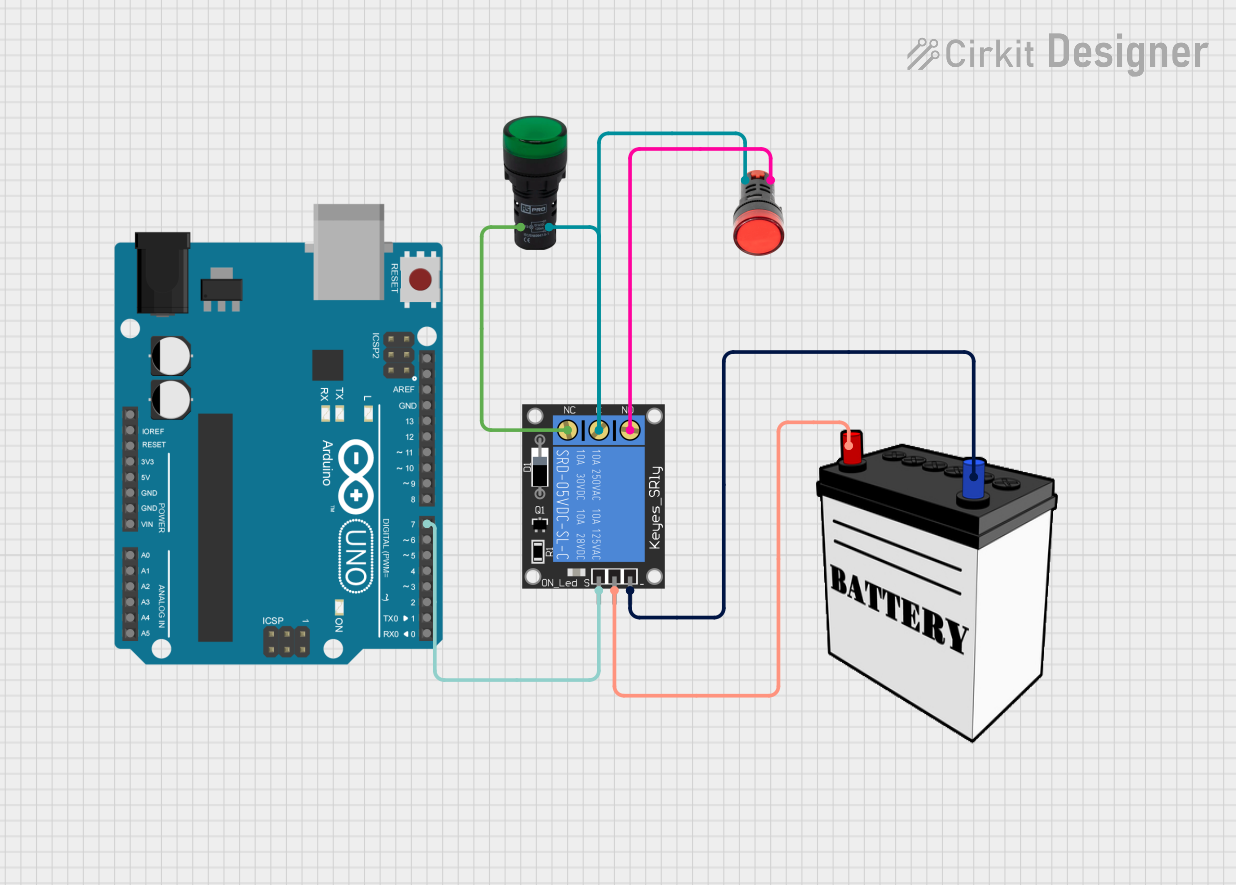
Note: The above code assumes the use of a low-voltage Pilot Lamp Red compatible with the Arduino's 5V output. If the lamp is rated for higher voltages, additional components such as a relay module will be required to interface with the Arduino safely.
Disclaimer: This documentation is for informational purposes only. Always consult the component's datasheet for the most accurate and detailed information.