How to Use Cytron 30Amp DC Motor Driver (Peak 80Amp) MD30C R2: Examples, Pinouts, and Specs
Introduction
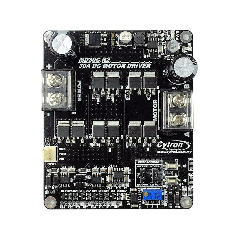
The Cytron 30Amp DC Motor Driver (MD30C R2) is a robust and reliable motor driver designed to control DC motors with a continuous current of up to 30A and a peak current of 80A. It is ideal for applications requiring high power and efficiency, such as robotics, automation systems, and electric vehicles. The MD30C R2 features a wide operating voltage range, multiple control modes, and built-in protection mechanisms, making it a versatile and user-friendly solution for motor control.
Explore Projects Built with Cytron 30Amp DC Motor Driver (Peak 80Amp) MD30C R2


Explore Projects Built with Cytron 30Amp DC Motor Driver (Peak 80Amp) MD30C R2
Common Applications and Use Cases
- Robotics (e.g., mobile robots, robotic arms)
- Conveyor belt systems
- Electric vehicles and carts
- Automated gates and doors
- Industrial automation and machinery
Technical Specifications
Key Technical Details
- Operating Voltage Range: 10V to 45V DC
- Continuous Current: 30A
- Peak Current: 80A (for 10 seconds)
- Control Modes:
- PWM (Pulse Width Modulation)
- Analog voltage
- RC (Radio Control) signal
- PWM Frequency: Up to 20kHz
- Logic Voltage: 3.3V or 5V compatible
- Built-in Protections: Overcurrent, overtemperature, and undervoltage
- Dimensions: 100mm x 70mm x 30mm
- Weight: 200g
Pin Configuration and Descriptions
The MD30C R2 has several input and output pins for motor control and power connections. Below is the pin configuration:
Input/Control Pins
| Pin Name | Type | Description |
|---|---|---|
PWM |
Input | PWM signal input for speed control (3.3V or 5V logic compatible). |
DIR |
Input | Direction control input (HIGH for forward, LOW for reverse). |
ANALOG |
Input | Analog voltage input for speed control (0-5V). |
RC |
Input | RC signal input for speed and direction control. |
GND |
Ground | Ground connection for logic signals. |
Power and Motor Connections
| Pin Name | Type | Description |
|---|---|---|
VM |
Power Input | Motor power supply (10V to 45V DC). |
GND |
Ground | Ground connection for motor power supply. |
M+ |
Output | Positive terminal of the motor. |
M- |
Output | Negative terminal of the motor. |
Usage Instructions
How to Use the Component in a Circuit
- Power Supply: Connect a DC power supply (10V to 45V) to the
VMandGNDpins. Ensure the power supply can handle the motor's current requirements. - Motor Connection: Connect the DC motor terminals to the
M+andM-pins. - Control Signal: Choose a control mode (PWM, Analog, or RC) and connect the corresponding input pin (
PWM,ANALOG, orRC) to your controller (e.g., Arduino, RC receiver). - Direction Control: Use the
DIRpin to set the motor's direction (HIGH for forward, LOW for reverse). - Grounding: Ensure all ground connections (
GND) are properly connected to avoid signal noise or damage.
Important Considerations and Best Practices
- Use appropriate wire gauges for power and motor connections to handle high currents.
- Ensure proper ventilation or cooling for the driver to prevent overheating during continuous operation.
- Avoid exceeding the voltage and current ratings to prevent damage to the driver or motor.
- Use a fuse or circuit breaker for additional protection in high-current applications.
- If using PWM control, ensure the PWM frequency is within the supported range (up to 20kHz).
Example: Connecting to an Arduino UNO
Below is an example of how to control the MD30C R2 using an Arduino UNO with PWM and direction control:
Circuit Connections
- Connect the
PWMpin of the MD30C R2 to Arduino pin9. - Connect the
DIRpin of the MD30C R2 to Arduino pin8. - Connect the
GNDpin of the MD30C R2 to the Arduino'sGND. - Connect the motor and power supply as described in the previous section.
Arduino Code
// Define pin connections
const int pwmPin = 9;  // PWM signal pin
const int dirPin = 8;  // Direction control pin

void setup() {
  // Set pin modes
  pinMode(pwmPin, OUTPUT);
  pinMode(dirPin, OUTPUT);
}

void loop() {
  // Set motor direction to forward
  digitalWrite(dirPin, HIGH);

  // Gradually increase motor speed
  for (int speed = 0; speed <= 255; speed++) {
    analogWrite(pwmPin, speed);  // Send PWM signal to control speed
    delay(20);                   // Wait for 20ms
  }

  // Hold maximum speed for 2 seconds
  delay(2000);

  // Gradually decrease motor speed
  for (int speed = 255; speed >= 0; speed--) {
    analogWrite(pwmPin, speed);  // Decrease PWM signal
    delay(20);
  }

  // Set motor direction to reverse
  digitalWrite(dirPin, LOW);

  // Repeat the same speed ramp-up and ramp-down process
  for (int speed = 0; speed <= 255; speed++) {
    analogWrite(pwmPin, speed);
    delay(20);
  }
  delay(2000);
  for (int speed = 255; speed >= 0; speed--) {
    analogWrite(pwmPin, speed);
    delay(20);
  }
}
Troubleshooting and FAQs
Common Issues and Solutions
Motor Not Running
- Cause: Incorrect wiring or loose connections.
- Solution: Double-check all connections, especially the power supply, motor, and control signals.
Overheating
- Cause: Prolonged operation at high currents without proper cooling.
- Solution: Ensure adequate ventilation or use a heatsink/fan for cooling.
Erratic Motor Behavior
- Cause: Noise or interference in control signals.
- Solution: Use shielded cables for signal connections and ensure proper grounding.
Driver Not Responding
- Cause: Exceeded voltage or current ratings, triggering protection mechanisms.
- Solution: Verify the power supply voltage and motor current requirements. Allow the driver to cool down if overtemperature protection is triggered.
FAQs
Q: Can I use a 12V battery to power the MD30C R2?
A: Yes, the MD30C R2 supports a voltage range of 10V to 45V, so a 12V battery is suitable.Q: What type of motors can I control with this driver?
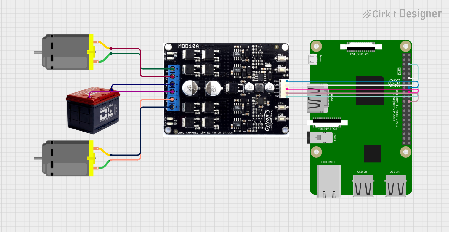
A: The MD30C R2 is designed for brushed DC motors.Q: Can I use this driver with a Raspberry Pi?
A: Yes, the MD30C R2 is compatible with 3.3V logic, making it suitable for use with a Raspberry Pi.Q: How do I reset the driver after a fault?
A: Remove power, check for the fault condition (e.g., overcurrent or overheating), and reconnect power after resolving the issue.