
How to Use USB Type-C 5V 2A Step-Up Boost Converter: Examples, Pinouts, and Specs
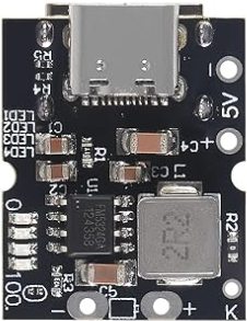
 Design with USB Type-C 5V 2A Step-Up Boost Converter in Cirkit Designer
Introduction
The USB Type-C 5V 2A Step-Up Boost Converter is an electronic module designed to increase a lower input voltage to a stable 5V output while delivering up to 2A of current. This component is commonly used to power USB devices, such as smartphones, tablets, and small electronics, from lower voltage sources like batteries or solar panels. Its compact design and USB Type-C interface make it ideal for portable and embedded applications.
Explore Projects Built with USB Type-C 5V 2A Step-Up Boost Converter
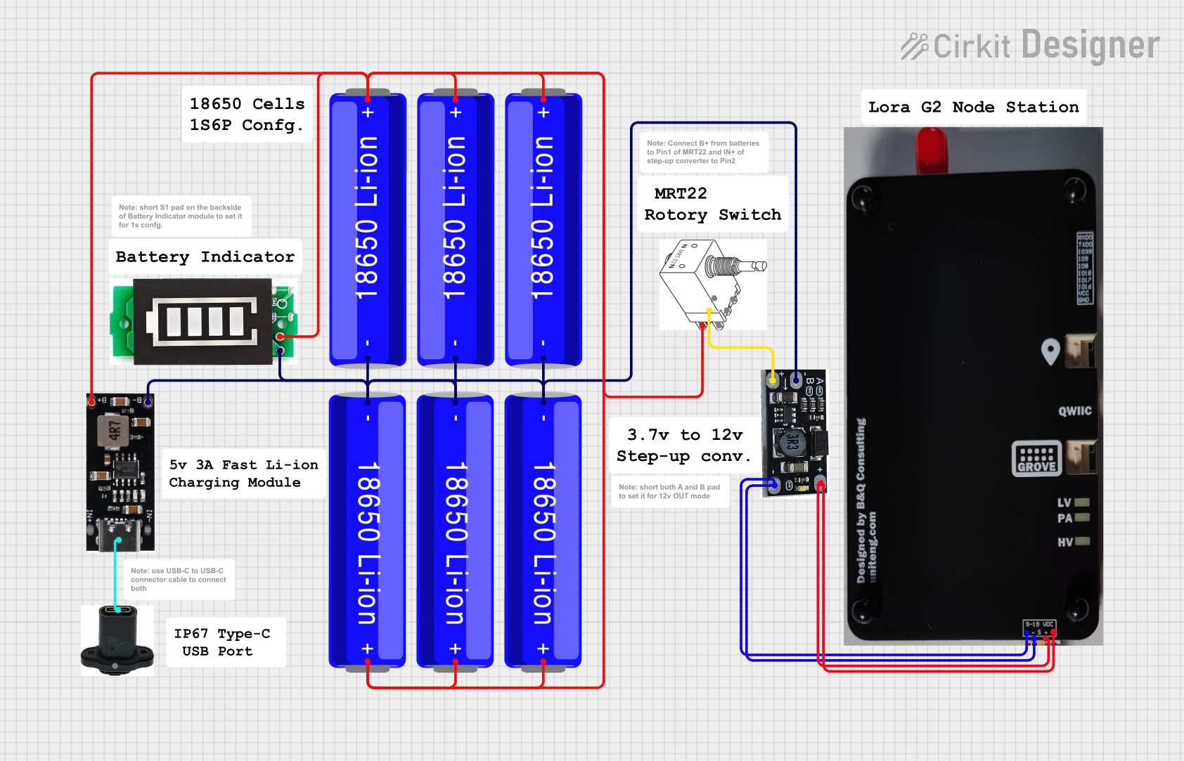 Open Project in Cirkit Designer
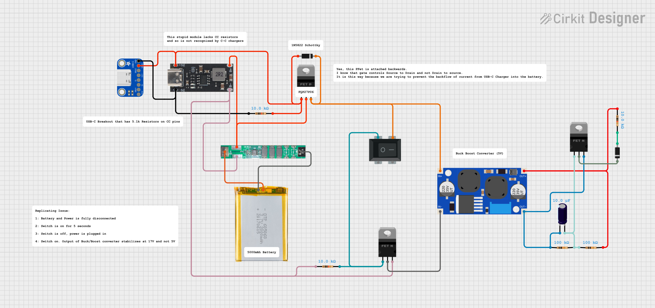 Open Project in Cirkit Designer
 Open Project in Cirkit Designer
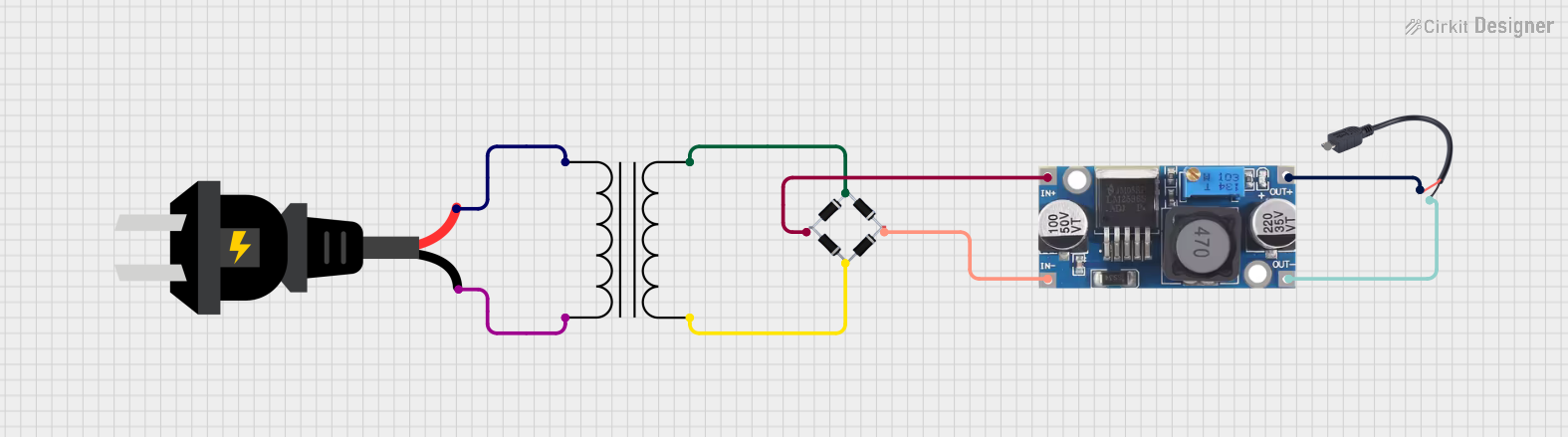 Open Project in Cirkit Designer
Explore Projects Built with USB Type-C 5V 2A Step-Up Boost Converter
Open Project in Cirkit DesignerOpen Project in Cirkit DesignerOpen Project in Cirkit DesignerOpen Project in Cirkit DesignerCommon Applications and Use Cases
- Powering USB devices from 3.7V lithium-ion batteries.
- Boosting voltage from solar panels for USB-powered devices.
- DIY power banks and portable chargers.
- Supplying stable 5V power to microcontrollers and development boards.
Technical Specifications
Key Technical Details
| Parameter | Value |
|---|---|
| Input Voltage Range | 2.5V to 4.5V |
| Output Voltage | 5V (regulated) |
| Maximum Output Current | 2A |
| Efficiency | Up to 92% |
| Connector Type | USB Type-C (output) |
| Dimensions | Typically 25mm x 15mm x 5mm |
| Operating Temperature | -40°C to 85°C |
Pin Configuration and Descriptions
| Pin Name | Description |
|---|---|
| VIN+ | Positive input voltage terminal (connect to the positive side of the source). |
| VIN- | Negative input voltage terminal (connect to the ground of the source). |
| USB Type-C | Output port providing 5V regulated power. |
Usage Instructions
How to Use the Component in a Circuit
Connect the Input Voltage Source:
- Attach the positive terminal of your power source (e.g., a 3.7V lithium-ion battery) to the
VIN+pin. - Connect the negative terminal of the power source to the
VIN-pin. - Ensure the input voltage is within the range of 2.5V to 4.5V.
- Attach the positive terminal of your power source (e.g., a 3.7V lithium-ion battery) to the
Connect the Load:
- Plug the USB device or cable into the USB Type-C output port.
- The module will automatically boost the input voltage to a stable 5V output.
Power On:
- Once the input voltage is applied, the module will begin regulating the output to 5V.
- Verify the output voltage using a multimeter if needed.
Important Considerations and Best Practices
- Input Voltage Range: Ensure the input voltage does not exceed 4.5V or drop below 2.5V to avoid damaging the module or causing unstable operation.
- Heat Dissipation: At higher currents (close to 2A), the module may generate heat. Ensure adequate ventilation or consider adding a small heatsink if necessary.
- Load Compatibility: Verify that the connected USB device does not draw more than 2A of current to prevent overloading the module.
- Polarity Protection: Double-check the polarity of the input connections to avoid damaging the module.
Example: Using with an Arduino UNO
The USB Type-C 5V 2A Step-Up Boost Converter can be used to power an Arduino UNO from a 3.7V lithium-ion battery. Here's how to set it up:
- Connect the battery's positive terminal to the
VIN+pin and the negative terminal to theVIN-pin. - Plug the USB Type-C output into the Arduino UNO's USB port.
- The Arduino UNO will now receive a stable 5V supply.
Sample Arduino Code
Below is a simple Arduino sketch to blink an LED while powered by the boost converter:
// This code blinks an LED connected to pin 13 of the Arduino UNO.
// Ensure the Arduino is powered via the USB Type-C boost converter.

void setup() {
  pinMode(13, OUTPUT); // Set pin 13 as an output pin
}

void loop() {
  digitalWrite(13, HIGH); // Turn the LED on
  delay(1000);            // Wait for 1 second
  digitalWrite(13, LOW);  // Turn the LED off
  delay(1000);            // Wait for 1 second
}
Troubleshooting and FAQs
Common Issues and Solutions
No Output Voltage:
- Cause: Incorrect input connections or insufficient input voltage.
- Solution: Verify the polarity of the input connections and ensure the input voltage is within the 2.5V to 4.5V range.
Output Voltage Drops Under Load:
- Cause: The connected load exceeds the 2A current limit.
- Solution: Reduce the load or use a device that draws less current.
Module Overheats:
- Cause: Prolonged operation at high current levels.
- Solution: Improve ventilation or add a heatsink to the module.
Device Does Not Charge:
- Cause: Incompatible USB cable or device requires more than 5V/2A.
- Solution: Use a compatible USB cable and ensure the device's power requirements are within the module's specifications.
FAQs
Can I use this module with a 1.5V battery?
No, the input voltage must be at least 2.5V for proper operation.Is the output voltage adjustable?
No, the output voltage is fixed at 5V.Can I use this module to power a Raspberry Pi?
It depends on the Raspberry Pi model. Most Raspberry Pi boards require more than 2A under load, so this module may not be suitable.Does the module have built-in short-circuit protection?
Some versions of this module include basic protection features, but it is recommended to verify the specific model's datasheet for details.