
How to Use MDB961WP-CAN-DroneCAN-28V: Examples, Pinouts, and Specs
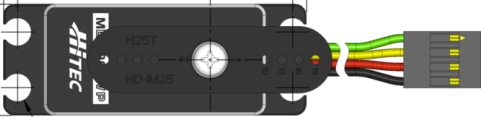
 Design with MDB961WP-CAN-DroneCAN-28V in Cirkit Designer
Introduction
The MDB961WP-CAN-DroneCAN-28V is a robust, high-performance CAN (Controller Area Network) interface module manufactured by Hitec. Designed specifically for drone applications, this module operates at 28V and facilitates reliable communication between various components in a drone system. Its rugged design ensures durability and consistent performance in demanding environments, making it an ideal choice for UAVs, robotics, and other embedded systems requiring efficient communication.
Explore Projects Built with MDB961WP-CAN-DroneCAN-28V
 Open Project in Cirkit Designer
 Open Project in Cirkit Designer
 Open Project in Cirkit Designer
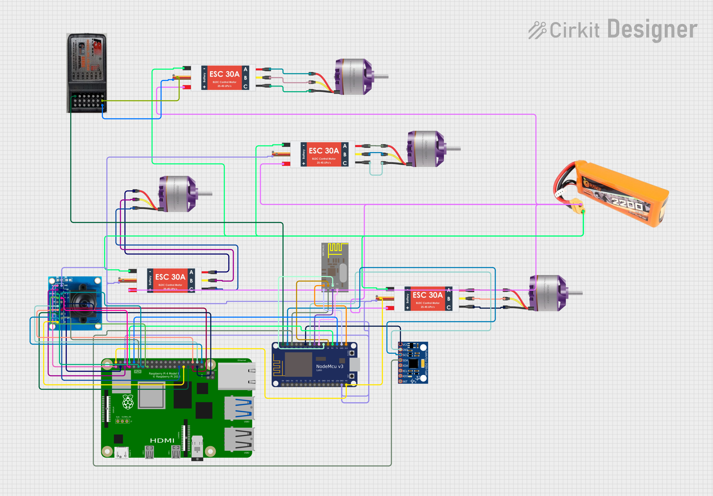 Open Project in Cirkit Designer
Explore Projects Built with MDB961WP-CAN-DroneCAN-28V
Open Project in Cirkit DesignerOpen Project in Cirkit DesignerOpen Project in Cirkit DesignerOpen Project in Cirkit DesignerCommon Applications and Use Cases
- Communication between drone flight controllers and peripheral devices (e.g., servos, sensors).
- Integration into UAV systems for real-time data exchange.
- Robotics systems requiring high-speed, reliable communication.
- Industrial automation systems utilizing the DroneCAN protocol.
- Applications requiring robust CAN communication in harsh environments.
Technical Specifications
Key Technical Details
| Parameter | Specification |
|---|---|
| Operating Voltage | 28V DC |
| Communication Protocol | DroneCAN (based on CAN 2.0B) |
| Maximum Current Consumption | 500mA |
| Operating Temperature Range | -40°C to +85°C |
| Dimensions | 50mm x 30mm x 15mm |
| Weight | 25g |
| Connector Type | JST-GH 4-pin |
| Baud Rate | Configurable (default: 1 Mbps) |
| Protection Features | Overvoltage, reverse polarity, ESD |
Pin Configuration and Descriptions
| Pin Number | Pin Name | Description |
|---|---|---|
| 1 | VCC | Power input (28V DC) |
| 2 | GND | Ground |
| 3 | CAN_H | CAN bus high signal |
| 4 | CAN_L | CAN bus low signal |
Usage Instructions
How to Use the Component in a Circuit
- Power Supply: Connect the VCC pin to a stable 28V DC power source and the GND pin to the ground of your system.
- CAN Bus Connection: Connect the CAN_H and CAN_L pins to the corresponding CAN bus lines in your system.
- Termination Resistor: Ensure that a 120-ohm termination resistor is present at each end of the CAN bus for proper signal integrity.
- Configuration: Use a compatible DroneCAN configuration tool to set the module's node ID and baud rate if required.
- Integration: Connect the module to your drone's flight controller or other CAN-enabled devices.
Important Considerations and Best Practices
- Voltage Compatibility: Ensure the power supply is precisely 28V DC to avoid damage.
- Wiring: Use shielded twisted-pair cables for the CAN bus to minimize noise and interference.
- Node ID: Assign a unique node ID to the module to prevent conflicts on the CAN network.
- Firmware Updates: Regularly check for firmware updates from Hitec to ensure optimal performance and compatibility.
- Environmental Protection: If used in harsh environments, ensure the module is adequately protected from moisture and debris.
Example Code for Arduino UNO
The MDB961WP-CAN-DroneCAN-28V can be interfaced with an Arduino UNO using a CAN transceiver module (e.g., MCP2515). Below is an example code snippet to send a message over the CAN bus:
#include <SPI.h>
#include <mcp_can.h>

// Define the SPI CS pin for the MCP2515 CAN module
#define CAN_CS_PIN 10

// Initialize the MCP_CAN object
MCP_CAN CAN(CAN_CS_PIN);

void setup() {
  Serial.begin(115200);
  while (!Serial);

  // Initialize the CAN bus at 1 Mbps
  if (CAN.begin(MCP_ANY, CAN_1000KBPS, MCP_8MHZ) == CAN_OK) {
    Serial.println("CAN bus initialized successfully!");
  } else {
    Serial.println("CAN bus initialization failed!");
    while (1);
  }

  // Set the CAN module to normal mode
  CAN.setMode(MCP_NORMAL);
  Serial.println("CAN module set to normal mode.");
}

void loop() {
  // Example message to send
  byte data[8] = {0x01, 0x02, 0x03, 0x04, 0x05, 0x06, 0x07, 0x08};

  // Send the message with ID 0x100
  if (CAN.sendMsgBuf(0x100, 0, 8, data) == CAN_OK) {
    Serial.println("Message sent successfully!");
  } else {
    Serial.println("Error sending message.");
  }

  delay(1000); // Wait 1 second before sending the next message
}
Troubleshooting and FAQs
Common Issues and Solutions
Module Not Powering On:
- Cause: Incorrect voltage or loose connections.
- Solution: Verify that the VCC pin is receiving 28V DC and that all connections are secure.
No Communication on CAN Bus:
- Cause: Incorrect wiring or missing termination resistors.
- Solution: Check the CAN_H and CAN_L connections and ensure 120-ohm termination resistors are present at both ends of the bus.
Conflicting Node IDs:
- Cause: Multiple devices on the CAN bus have the same node ID.
- Solution: Assign a unique node ID to each device using a DroneCAN configuration tool.
High Noise on CAN Bus:
- Cause: Unshielded cables or improper grounding.
- Solution: Use shielded twisted-pair cables and ensure proper grounding of all devices.
FAQs
Q1: Can this module operate at voltages other than 28V?
A1: No, the module is designed to operate specifically at 28V DC. Using other voltages may damage the module.
Q2: Is the module compatible with other CAN protocols?
A2: The module is optimized for DroneCAN, but it may work with other CAN 2.0B-based protocols with proper configuration.
Q3: How do I update the firmware?
A3: Firmware updates can be performed using a DroneCAN-compatible tool. Refer to the manufacturer's website for detailed instructions.
Q4: Can I use this module in non-drone applications?
A4: Yes, the module can be used in any system requiring robust CAN communication, provided the voltage and protocol requirements are met.