How to Use Teensy 4.0 Bottom SMT: Examples, Pinouts, and Specs
Introduction
The Teensy 4.0 Bottom SMT, manufactured by PJRC, is a compact and high-performance microcontroller board designed for rapid prototyping and embedded applications. It features a powerful 600 MHz ARM Cortex-M7 processor, making it ideal for projects requiring high computational power and real-time processing. The Bottom SMT variant is specifically designed for surface-mount applications, allowing for a more compact and robust integration into custom PCBs.
Explore Projects Built with Teensy 4.0 Bottom SMT
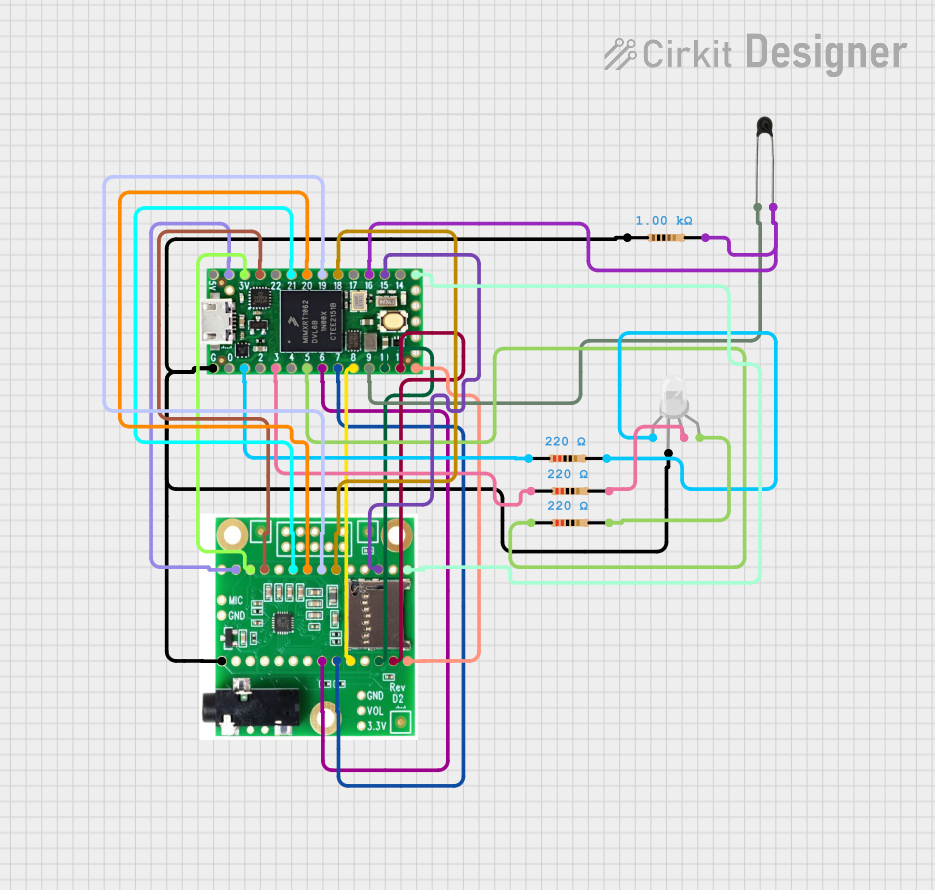
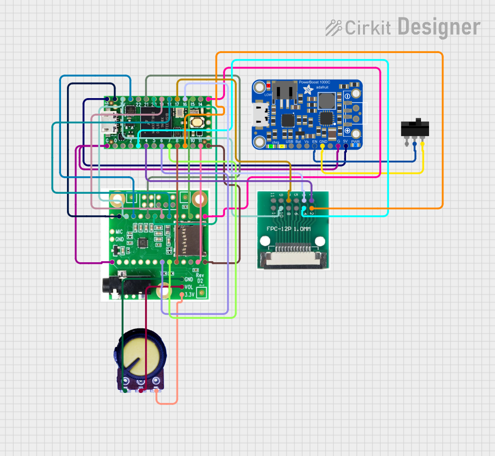
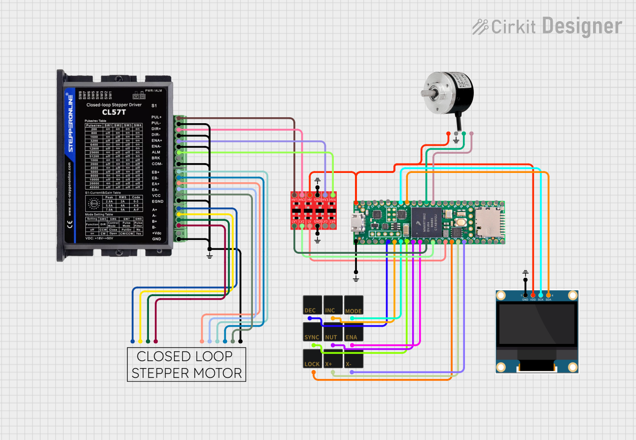

Explore Projects Built with Teensy 4.0 Bottom SMT
Common Applications and Use Cases
- Robotics and automation systems
- Audio processing and synthesis
- High-speed data acquisition
- IoT (Internet of Things) devices
- Advanced motor control
- Machine learning and AI applications
- Custom embedded systems
Technical Specifications
Key Technical Details
- Processor: ARM Cortex-M7, 600 MHz
- Flash Memory: 2 MB
- RAM: 1 MB
- EEPROM: 4 KB (emulated)
- Operating Voltage: 3.3V
- Input Voltage Range: 3.6V to 5.5V
- Digital I/O Pins: 40 (35 PWM-capable)
- Analog Input Pins: 14 (12-bit ADC)
- Communication Interfaces: UART, SPI, I2C, CAN, USB (Host/Device)
- Clock Speed: 600 MHz (with dynamic scaling)
- Dimensions: 1.4 x 0.7 inches (35.56 x 17.78 mm)
- Temperature Range: -40°C to 85°C
Pin Configuration and Descriptions
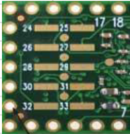
The Teensy 4.0 Bottom SMT has a total of 48 pads, including power, ground, and I/O pins. Below is a summary of the pin configuration:
Power and Ground Pins
| Pin Name | Description |
|---|---|
| VIN | Input voltage (3.6V to 5.5V) |
| 3.3V | Regulated 3.3V output |
| GND | Ground |
Digital and PWM Pins
| Pin Name | Description |
|---|---|
| D0-D39 | Digital I/O pins (PWM on D0-D34) |
| D13 | Onboard LED (active HIGH) |
Analog Pins
| Pin Name | Description |
|---|---|
| A0-A13 | Analog input pins (12-bit resolution) |
Communication Pins
| Pin Name | Description |
|---|---|
| TX1/RX1 | UART Serial 1 |
| TX2/RX2 | UART Serial 2 |
| TX3/RX3 | UART Serial 3 |
| SCL/SDA | I2C communication |
| MOSI/MISO/SCK | SPI communication |
| CANRX/CANTX | CAN bus communication |
USB and Special Function Pins
| Pin Name | Description |
|---|---|
| USB+ | USB data positive |
| USB- | USB data negative |
| RESET | Reset pin |
| PROGRAM | Enter bootloader mode |
Usage Instructions
How to Use the Teensy 4.0 Bottom SMT in a Circuit
Powering the Board:
- Provide a regulated 3.6V to 5.5V input to the VIN pin. The onboard regulator will supply 3.3V to the microcontroller.
- Alternatively, you can power the board directly via the 3.3V pin if an external regulator is used.
Programming the Board:
- Install the Arduino IDE and the Teensyduino add-on from PJRC's website.
- Connect the Teensy 4.0 to your computer via USB.
- Select "Teensy 4.0" as the board in the Arduino IDE and upload your code.
Connecting Peripherals:
- Use the digital I/O pins for interfacing with sensors, actuators, and other devices.
- For analog inputs, connect sensors to the A0-A13 pins.
- Use the communication pins (UART, SPI, I2C, CAN) for advanced interfacing.
Surface-Mount Integration:
- Solder the Teensy 4.0 Bottom SMT onto a custom PCB using the provided pads.
- Ensure proper alignment and use a reflow soldering process for best results.
Important Considerations and Best Practices
- Voltage Levels: All I/O pins operate at 3.3V logic levels. Do not apply 5V directly to any I/O pin.
- Heat Dissipation: For high-performance applications, ensure adequate heat dissipation to prevent overheating.
- Bootloader Mode: Use the PROGRAM pin to manually enter bootloader mode if needed.
- Static Protection: Handle the board with care to avoid damage from electrostatic discharge (ESD).
Example Code for Arduino IDE
The following example demonstrates how to blink the onboard LED (D13):
// Blink the onboard LED on Teensy 4.0
const int ledPin = 13; // Onboard LED is connected to pin 13

void setup() {
  pinMode(ledPin, OUTPUT); // Set pin 13 as an output
}

void loop() {
  digitalWrite(ledPin, HIGH); // Turn the LED on
  delay(500);                 // Wait for 500 milliseconds
  digitalWrite(ledPin, LOW);  // Turn the LED off
  delay(500);                 // Wait for 500 milliseconds
}
Troubleshooting and FAQs
Common Issues and Solutions
Board Not Recognized by Computer:
- Ensure the USB cable is functional and supports data transfer.
- Check if the board is in bootloader mode by pressing the PROGRAM button.
Code Upload Fails:
- Verify that "Teensy 4.0" is selected as the board in the Arduino IDE.
- Ensure the Teensyduino add-on is installed correctly.
Overheating:
- Check for excessive current draw from connected peripherals.
- Ensure proper ventilation or add a heatsink if necessary.
I/O Pins Not Responding:
- Confirm that the pins are configured correctly in your code.
- Check for short circuits or incorrect wiring.
FAQs
Q: Can I use 5V sensors with the Teensy 4.0?
A: Yes, but you must use a level shifter to convert 5V signals to 3.3V logic levels.
Q: How do I reset the Teensy 4.0?
A: You can reset the board by briefly connecting the RESET pin to GND.
Q: Is the Teensy 4.0 compatible with Arduino libraries?
A: Most Arduino libraries are compatible, but some may require modifications for the ARM Cortex-M7 architecture.
Q: Can I use the Teensy 4.0 for audio processing?
A: Absolutely! The Teensy 4.0 is well-suited for audio applications and supports the PJRC Audio Library.
This concludes the documentation for the Teensy 4.0 Bottom SMT. For further details, refer to the official PJRC website.