Cirkit Designer Logo
Cirkit Designer
Your all-in-one circuit design IDE
Home / 
Component Documentation

How to Use VL6180X(NY): Examples, Pinouts, and Specs

Image of VL6180X(NY)
Cirkit Designer LogoDesign with VL6180X(NY) in Cirkit Designer

Introduction

The VL6180X is a time-of-flight (ToF) distance sensor capable of measuring distances up to 100 mm with high accuracy. It integrates an infrared emitter and a photodetector, enabling it to detect proximity and ambient light levels. This sensor is widely used in robotics, automation, and consumer electronics for applications such as obstacle detection, gesture recognition, and ambient light sensing.

Explore Projects Built with VL6180X(NY)

Use Cirkit Designer to design, explore, and prototype these projects online. Some projects support real-time simulation. Click "Open Project" to start designing instantly!
Arduino Nano Based GPS Tracker with GSM Communication and Accelerometer
Image of Circuit Aayush: A project utilizing VL6180X(NY) in a practical application
This circuit is designed for communication and location tracking purposes. It features an Arduino Nano interfaced with a SIM800L GSM module for cellular connectivity, a GPS NEO 6M module for obtaining geographical coordinates, and an AITrip ADXL335 GY-61 accelerometer for motion sensing. The LM2596 Step Down Module is used to regulate the power supply to the components.
Cirkit Designer LogoOpen Project in Cirkit Designer
Nucleo 401RE Controlled Robotic Motor with Vibration Feedback and ADXL345 Accelerometer
Image of MLKIT: A project utilizing VL6180X(NY) in a practical application
This circuit features a Nucleo 401RE microcontroller as the central processing unit, interfacing with an ADXL345 accelerometer and an INA219 current sensor over an I2C bus for motion sensing and power monitoring, respectively. A DC motor with an encoder is driven by an L298N motor driver, with speed control potentially provided by a connected potentiometer and vibration feedback through a vibration motor. The system is powered by a 12V battery, with voltage regulation provided for the various components.
Cirkit Designer LogoOpen Project in Cirkit Designer
Cellular-Enabled IoT Device with Real-Time Clock and Power Management
Image of LRCM PHASE 2 BASIC: A project utilizing VL6180X(NY) in a practical application
This circuit features a LilyGo-SIM7000G module for cellular communication and GPS functionality, interfaced with an RTC DS3231 for real-time clock capabilities. It includes voltage sensing through two voltage sensor modules, and uses an 8-channel opto-coupler for isolating different parts of the circuit. Power management is handled by a buck converter connected to a DC power source and batteries, with a fuse for protection and a rocker switch for on/off control. Additionally, there's an LED for indication purposes.
Cirkit Designer LogoOpen Project in Cirkit Designer
Battery-Powered Emergency Alert System with NUCLEO-F072RB, SIM800L, and GPS NEO 6M
Image of women safety: A project utilizing VL6180X(NY) in a practical application
This circuit is an emergency alert system that uses a NUCLEO-F072RB microcontroller to send SMS alerts and make calls via a SIM800L GSM module, while obtaining location data from a GPS NEO 6M module. The system is powered by a Li-ion battery and includes a TP4056 module for battery charging and protection, with a rocker switch to control power to the microcontroller.
Cirkit Designer LogoOpen Project in Cirkit Designer

Explore Projects Built with VL6180X(NY)

Use Cirkit Designer to design, explore, and prototype these projects online. Some projects support real-time simulation. Click "Open Project" to start designing instantly!
Image of Circuit Aayush: A project utilizing VL6180X(NY) in a practical application
Arduino Nano Based GPS Tracker with GSM Communication and Accelerometer
This circuit is designed for communication and location tracking purposes. It features an Arduino Nano interfaced with a SIM800L GSM module for cellular connectivity, a GPS NEO 6M module for obtaining geographical coordinates, and an AITrip ADXL335 GY-61 accelerometer for motion sensing. The LM2596 Step Down Module is used to regulate the power supply to the components.
Cirkit Designer LogoOpen Project in Cirkit Designer
Image of MLKIT: A project utilizing VL6180X(NY) in a practical application
Nucleo 401RE Controlled Robotic Motor with Vibration Feedback and ADXL345 Accelerometer
This circuit features a Nucleo 401RE microcontroller as the central processing unit, interfacing with an ADXL345 accelerometer and an INA219 current sensor over an I2C bus for motion sensing and power monitoring, respectively. A DC motor with an encoder is driven by an L298N motor driver, with speed control potentially provided by a connected potentiometer and vibration feedback through a vibration motor. The system is powered by a 12V battery, with voltage regulation provided for the various components.
Cirkit Designer LogoOpen Project in Cirkit Designer
Image of LRCM PHASE 2 BASIC: A project utilizing VL6180X(NY) in a practical application
Cellular-Enabled IoT Device with Real-Time Clock and Power Management
This circuit features a LilyGo-SIM7000G module for cellular communication and GPS functionality, interfaced with an RTC DS3231 for real-time clock capabilities. It includes voltage sensing through two voltage sensor modules, and uses an 8-channel opto-coupler for isolating different parts of the circuit. Power management is handled by a buck converter connected to a DC power source and batteries, with a fuse for protection and a rocker switch for on/off control. Additionally, there's an LED for indication purposes.
Cirkit Designer LogoOpen Project in Cirkit Designer
Image of women safety: A project utilizing VL6180X(NY) in a practical application
Battery-Powered Emergency Alert System with NUCLEO-F072RB, SIM800L, and GPS NEO 6M
This circuit is an emergency alert system that uses a NUCLEO-F072RB microcontroller to send SMS alerts and make calls via a SIM800L GSM module, while obtaining location data from a GPS NEO 6M module. The system is powered by a Li-ion battery and includes a TP4056 module for battery charging and protection, with a rocker switch to control power to the microcontroller.
Cirkit Designer LogoOpen Project in Cirkit Designer

Common Applications:

  • Obstacle detection in robotics
  • Gesture recognition in smart devices
  • Proximity sensing in automation systems
  • Ambient light level measurement for display brightness adjustment

Technical Specifications

Below are the key technical details of the VL6180X sensor:

Parameter Value
Operating Voltage 2.6 V to 3.3 V
Communication Interface I2C
Maximum Distance Range 100 mm
Ambient Light Sensing Yes
Infrared Wavelength 850 nm
Current Consumption 1.7 mA (typical)
Operating Temperature -20°C to +70°C
Package Type Optical LGA12 (4.8 mm x 2.8 mm)

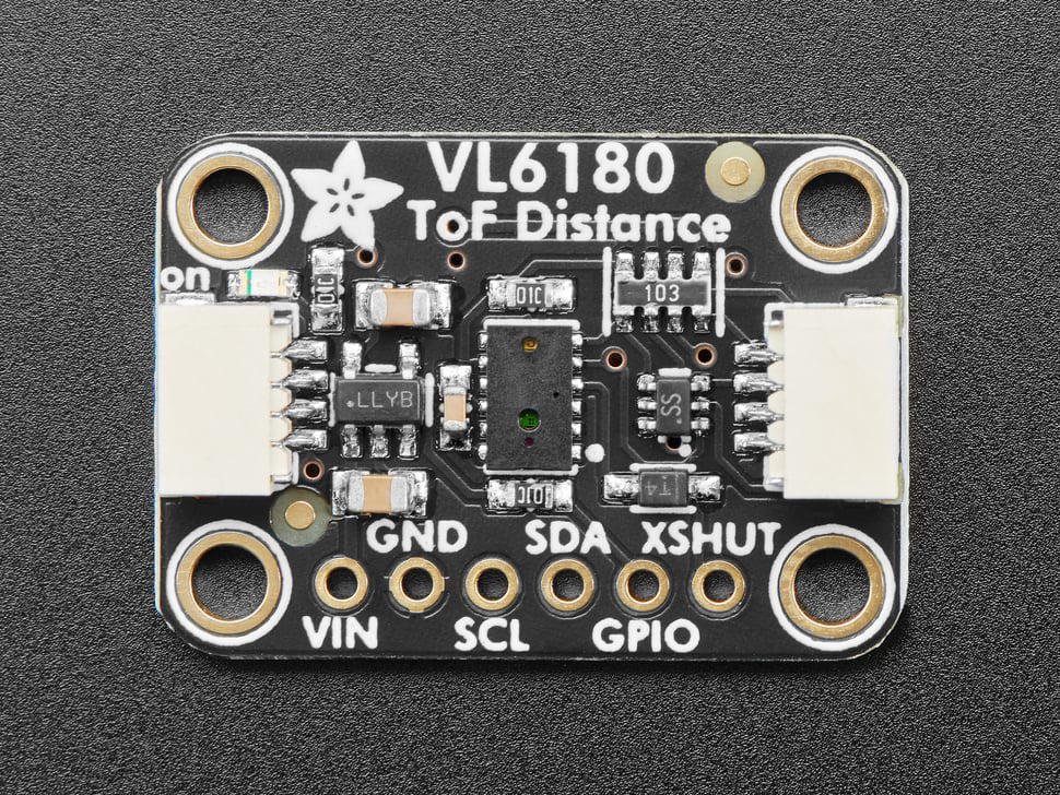
Pin Configuration and Descriptions

The VL6180X has 12 pins, but only a subset is typically used in most applications. Below is the pin configuration:

Pin Name Pin Number Description
GND 1 Ground
VDD 2 Power supply (2.6 V to 3.3 V)
SCL 3 I2C clock line
SDA 4 I2C data line
GPIO0 5 General-purpose I/O (interrupt output)
GPIO1 6 General-purpose I/O
XSHUT 7 Shutdown pin (active low)
NC 8-12 Not connected

Usage Instructions

How to Use the VL6180X in a Circuit

  1. Power Supply: Connect the VDD pin to a 3.3 V power source and the GND pin to ground.
  2. I2C Communication: Connect the SCL and SDA pins to the corresponding I2C lines of your microcontroller. Use pull-up resistors (typically 4.7 kΩ) on both lines.
  3. Interrupt Pin (Optional): Connect GPIO0 to your microcontroller if you want to use the interrupt feature for event detection.
  4. Shutdown Pin: Connect the XSHUT pin to your microcontroller or pull it high to enable the sensor. Pull it low to place the sensor in shutdown mode.

Important Considerations:

  • I2C Address: The default I2C address of the VL6180X is 0x29. Ensure no other devices on the I2C bus share this address.
  • Distance Limitations: The sensor is optimized for distances up to 100 mm. Beyond this range, accuracy may degrade.
  • Ambient Light: Avoid placing the sensor in direct sunlight or near strong infrared sources, as this may affect performance.

Example Code for Arduino UNO

Below is an example of how to interface the VL6180X with an Arduino UNO using the Adafruit VL6180X library:

#include <Wire.h>
#include "Adafruit_VL6180X.h"

// Create an instance of the VL6180X sensor
Adafruit_VL6180X vl = Adafruit_VL6180X();

void setup() {
  Serial.begin(9600); // Initialize serial communication
  Serial.println("VL6180X Test");

  if (!vl.begin()) {
    // If the sensor is not detected, print an error message
    Serial.println("Failed to find VL6180X chip");
    while (1); // Halt execution
  }
  Serial.println("VL6180X Found!");
}

void loop() {
  // Read the distance in millimeters
  uint8_t range = vl.readRange();
  uint8_t status = vl.readRangeStatus();

  if (status == VL6180X_ERROR_NONE) {
    // Print the distance if no error is detected
    Serial.print("Range: ");
    Serial.print(range);
    Serial.println(" mm");
  } else {
    // Print an error message if there is an issue
    Serial.print("Range error: ");
    Serial.println(status);
  }

  delay(500); // Wait for 500 ms before the next reading
}

Notes:

  • Install the Adafruit VL6180X library via the Arduino Library Manager before running the code.
  • Ensure proper pull-up resistors are connected to the I2C lines.

Troubleshooting and FAQs

Common Issues and Solutions

  1. Sensor Not Detected on I2C Bus:

    • Ensure the sensor is powered correctly (check VDD and GND connections).
    • Verify the I2C pull-up resistors are in place.
    • Check that the XSHUT pin is pulled high to enable the sensor.
  2. Incorrect Distance Measurements:

    • Ensure the sensor is within its operating range (up to 100 mm).
    • Avoid reflective or transparent surfaces directly in front of the sensor.
    • Minimize ambient infrared interference.
  3. Intermittent Readings:

    • Check for loose connections on the I2C lines.
    • Verify that the I2C clock speed is set to 100 kHz or 400 kHz.

FAQs

Q: Can the VL6180X measure distances beyond 100 mm?
A: The VL6180X is optimized for distances up to 100 mm. While it may detect objects slightly beyond this range, accuracy is not guaranteed.

Q: Can I use the VL6180X with a 5 V microcontroller?
A: Yes, but you must use a level shifter for the I2C lines and ensure the sensor's VDD pin is supplied with 3.3 V.

Q: How do I reset the sensor?
A: Pull the XSHUT pin low for at least 1 ms, then pull it high to reset the sensor.

By following this documentation, you can effectively integrate the VL6180X into your projects and troubleshoot common issues.