
How to Use Header 6: Examples, Pinouts, and Specs
 Design with Header 6 in Cirkit Designer
Introduction
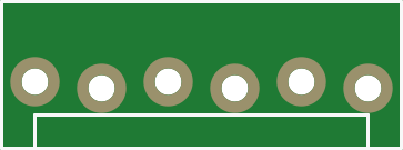
A Header 6 is a type of connector used in electronic circuits, typically featuring six pins arranged in a single or dual row. It is designed to facilitate the connection of various components or devices, enabling communication, signal transmission, and power distribution. Header 6 connectors are widely used in prototyping, development boards, and embedded systems due to their simplicity and versatility.
Explore Projects Built with Header 6
 Open Project in Cirkit Designer
 Open Project in Cirkit Designer
 Open Project in Cirkit Designer
 Open Project in Cirkit Designer
Explore Projects Built with Header 6
Open Project in Cirkit DesignerOpen Project in Cirkit DesignerOpen Project in Cirkit DesignerOpen Project in Cirkit DesignerCommon Applications and Use Cases
- Connecting sensors, modules, or peripherals to microcontrollers (e.g., Arduino, Raspberry Pi)
- Power and signal distribution in breadboard or PCB-based circuits
- Interfacing with communication protocols such as I2C, SPI, or UART
- Modular designs where components need to be easily connected or replaced
Technical Specifications
Key Technical Details
- Number of Pins: 6
- Pin Pitch: 2.54 mm (standard spacing)
- Current Rating: Typically up to 3A per pin (varies by manufacturer)
- Voltage Rating: Typically up to 250V (varies by manufacturer)
- Material: Gold-plated or tin-plated copper alloy for pins; plastic housing
- Temperature Range: -40°C to +105°C (varies by manufacturer)
- Mounting Type: Through-hole or surface-mount
Pin Configuration and Descriptions
The Header 6 connector consists of six pins, which can be configured for various purposes depending on the circuit design. Below is a general example of pin usage in a typical application:
| Pin Number | Description | Example Use |
|---|---|---|
| 1 | Power (VCC) | Supplies power to the circuit |
| 2 | Ground (GND) | Common ground connection |
| 3 | Signal/Data Line 1 | Communication or control signal |
| 4 | Signal/Data Line 2 | Communication or control signal |
| 5 | Signal/Data Line 3 | Communication or control signal |
| 6 | Signal/Data Line 4 | Communication or control signal |
Note: The specific pin assignments may vary depending on the application or device being connected. Always refer to the datasheet or schematic for proper configuration.
Usage Instructions
How to Use the Header 6 in a Circuit
- Identify Pin Assignments: Determine the function of each pin based on your circuit design or the device's datasheet.
- Soldering: If using a through-hole Header 6, solder the pins to the PCB. For surface-mount headers, use appropriate soldering techniques.
- Connection: Insert the corresponding male or female connector into the Header 6 to establish a secure connection.
- Verify Connections: Double-check the connections to ensure proper alignment and avoid short circuits.
Important Considerations and Best Practices
- Pin Alignment: Ensure the pins are aligned correctly with the mating connector to prevent damage.
- Current and Voltage Ratings: Do not exceed the specified current and voltage ratings to avoid overheating or failure.
- Mechanical Stress: Avoid applying excessive force or bending the pins, as this can damage the connector.
- Signal Integrity: For high-speed signals, minimize the length of the connection to reduce noise and interference.
Example: Connecting Header 6 to an Arduino UNO
Below is an example of how to use a Header 6 to connect a sensor module to an Arduino UNO:
Circuit Diagram
- Pin 1 (VCC) → Arduino 5V
- Pin 2 (GND) → Arduino GND
- Pin 3 (Signal 1) → Arduino Digital Pin 2
- Pin 4 (Signal 2) → Arduino Digital Pin 3
- Pin 5 (Signal 3) → Arduino Digital Pin 4
- Pin 6 (Signal 4) → Arduino Digital Pin 5
Arduino Code Example
// Example code for reading signals from a Header 6-connected sensor module

const int signalPin1 = 2; // Pin 3 of Header 6 connected to Digital Pin 2
const int signalPin2 = 3; // Pin 4 of Header 6 connected to Digital Pin 3
const int signalPin3 = 4; // Pin 5 of Header 6 connected to Digital Pin 4
const int signalPin4 = 5; // Pin 6 of Header 6 connected to Digital Pin 5

void setup() {
  // Initialize serial communication for debugging
  Serial.begin(9600);

  // Set signal pins as inputs
  pinMode(signalPin1, INPUT);
  pinMode(signalPin2, INPUT);
  pinMode(signalPin3, INPUT);
  pinMode(signalPin4, INPUT);
}

void loop() {
  // Read values from the signal pins
  int value1 = digitalRead(signalPin1);
  int value2 = digitalRead(signalPin2);
  int value3 = digitalRead(signalPin3);
  int value4 = digitalRead(signalPin4);

  // Print the values to the Serial Monitor
  Serial.print("Signal 1: ");
  Serial.println(value1);
  Serial.print("Signal 2: ");
  Serial.println(value2);
  Serial.print("Signal 3: ");
  Serial.println(value3);
  Serial.print("Signal 4: ");
  Serial.println(value4);

  delay(1000); // Wait for 1 second before reading again
}
Troubleshooting and FAQs
Common Issues Users Might Face
- Loose Connections: The mating connector may not fit securely, causing intermittent signals.
- Solution: Ensure the connector is fully inserted and properly aligned.
- Short Circuits: Adjacent pins may accidentally touch due to poor soldering or misalignment.
- Solution: Inspect the solder joints and use heat shrink tubing or insulation if necessary.
- Signal Noise or Interference: Long wires or poor grounding can introduce noise.
- Solution: Use shorter wires and ensure a solid ground connection.
- Overheating: Exceeding the current rating can cause the connector to overheat.
- Solution: Verify the current requirements of your circuit and use appropriate connectors.
FAQs
Q: Can I use a Header 6 for high-frequency signals?
A: Yes, but ensure the connections are short and properly shielded to minimize interference.
Q: Are Header 6 connectors polarized?
A: No, Header 6 connectors are not inherently polarized. Be cautious to connect them in the correct orientation.
Q: Can I use a Header 6 for power distribution?
A: Yes, as long as the current and voltage ratings are not exceeded. For higher currents, consider using thicker pins or dedicated power connectors.
Q: How do I remove a Header 6 from a PCB?
A: Use a soldering iron and desoldering pump or wick to carefully remove the solder from each pin, then gently pull the connector out.
By following this documentation, you can effectively use a Header 6 connector in your electronic projects!