Cirkit Designer
Your all-in-one circuit design IDE
Home /
Component Documentation
How to Use lcd: Examples, Pinouts, and Specs
Introduction
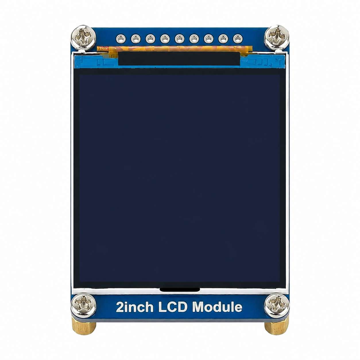
- A Liquid Crystal Display (LCD) is a flat-panel display technology that uses liquid crystals to modulate light. It is widely used in various electronic devices due to its low power consumption, lightweight design, and ability to produce sharp and clear images.
- Common applications include:
- Digital displays for televisions, computer monitors, and mobile devices.
- Embedded systems for displaying information (e.g., temperature, time, or sensor data).
- User interfaces in appliances, calculators, and industrial equipment.
- Prototyping and hobbyist projects, especially with microcontrollers like Arduino.
Explore Projects Built with lcd
Arduino Nano and I2C LCD Display Power Supply Project

This circuit features an Arduino Nano microcontroller interfaced with a 20x4 I2C LCD panel for display purposes. The LCD panel is powered by a 5V AC-DC power supply unit, and the Arduino Nano communicates with the LCD via I2C protocol using its A5 (SDA) and A1 (SCL) pins.
ESP32-Controlled Multi-Display Interactive System with Pushbutton Inputs

This circuit consists of multiple GC9A01 display modules interfaced with an ESP32 microcontroller. The ESP32 controls the reset (RST), chip select (CS), data/command (DC), serial data (SDA), and serial clock (SCL) lines of each display, allowing for individual communication with each screen. Additionally, there are pushbuttons connected to the ESP32, which could be used for user input to control the displays or other functions within the circuit.
ESP32-S3 and ILI9488 TFT LCD Display for Interactive Graphics
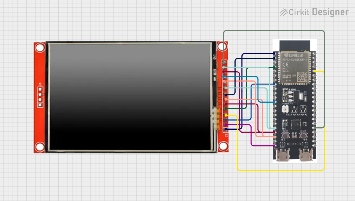
This circuit features an ESP32-S3 microcontroller connected to an ILI9488 TFT LCD display. The ESP32-S3 initializes and controls the display, demonstrating basic graphics and text rendering using the TFT_eSPI library.
Arduino UNO Controlled LCD Display with Adjustable Contrast
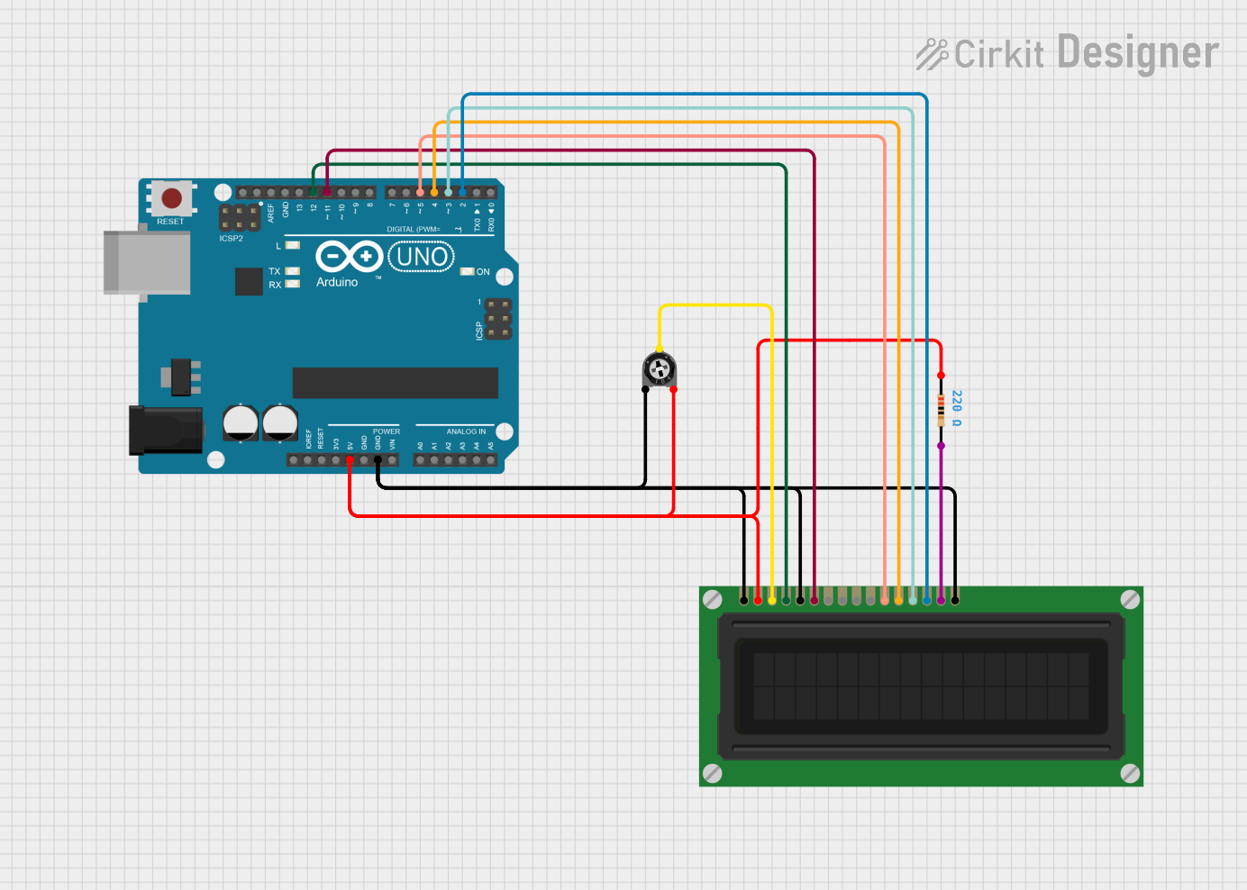
This circuit features an Arduino UNO connected to a 16x2 LCD display for text output. The Arduino controls the display via digital pins D2 to D5 for data transmission and pins D11 and D12 for enable and register select signals. A trimmer potentiometer adjusts the display contrast, and a resistor provides current limiting for the LCD backlight.
Explore Projects Built with lcd
Arduino Nano and I2C LCD Display Power Supply Project
This circuit features an Arduino Nano microcontroller interfaced with a 20x4 I2C LCD panel for display purposes. The LCD panel is powered by a 5V AC-DC power supply unit, and the Arduino Nano communicates with the LCD via I2C protocol using its A5 (SDA) and A1 (SCL) pins.
ESP32-Controlled Multi-Display Interactive System with Pushbutton Inputs
This circuit consists of multiple GC9A01 display modules interfaced with an ESP32 microcontroller. The ESP32 controls the reset (RST), chip select (CS), data/command (DC), serial data (SDA), and serial clock (SCL) lines of each display, allowing for individual communication with each screen. Additionally, there are pushbuttons connected to the ESP32, which could be used for user input to control the displays or other functions within the circuit.
ESP32-S3 and ILI9488 TFT LCD Display for Interactive Graphics
This circuit features an ESP32-S3 microcontroller connected to an ILI9488 TFT LCD display. The ESP32-S3 initializes and controls the display, demonstrating basic graphics and text rendering using the TFT_eSPI library.
Arduino UNO Controlled LCD Display with Adjustable Contrast
This circuit features an Arduino UNO connected to a 16x2 LCD display for text output. The Arduino controls the display via digital pins D2 to D5 for data transmission and pins D11 and D12 for enable and register select signals. A trimmer potentiometer adjusts the display contrast, and a resistor provides current limiting for the LCD backlight.
Technical Specifications
- Display Type: Alphanumeric or Graphical
- Operating Voltage: Typically 5V DC (some models support 3.3V)
- Current Consumption: ~1-2 mA (without backlight), ~15-20 mA (with backlight)
- Interface: Parallel (4-bit or 8-bit mode) or I2C (for modules with an I2C adapter)
- Character Size: Commonly 5x8 or 5x10 dot matrix
- Backlight: LED (optional, for improved visibility in low light)
- Temperature Range: -20°C to 70°C (varies by model)
Pin Configuration and Descriptions
Below is the pin configuration for a standard 16x2 LCD module (HD44780-compatible):
| Pin No. | Name | Description |
|---|---|---|
| 1 | VSS | Ground (0V) connection |
| 2 | VDD | Power supply (typically 5V) |
| 3 | V0 | Contrast adjustment (connect to a potentiometer for contrast control) |
| 4 | RS | Register Select (0: Command mode, 1: Data mode) |
| 5 | RW | Read/Write (0: Write to LCD, 1: Read from LCD) |
| 6 | E | Enable pin (triggers data read/write when toggled) |
| 7-14 | D0-D7 | Data pins (used for sending commands/data in 4-bit or 8-bit mode) |
| 15 | LED+ | Backlight anode (connect to 5V via a resistor if backlight is used) |
| 16 | LED- | Backlight cathode (connect to ground if backlight is used) |
For I2C-based LCD modules, the pin configuration is simplified:
| Pin No. | Name | Description |
|---|---|---|
| 1 | GND | Ground (0V) connection |
| 2 | VCC | Power supply (typically 5V or 3.3V) |
| 3 | SDA | Serial Data Line (I2C communication) |
| 4 | SCL | Serial Clock Line (I2C communication) |
Usage Instructions
Connecting the LCD to an Arduino UNO
Wiring for Parallel Interface (4-bit mode):
- Connect the LCD pins as follows:
- VSS → GND
- VDD → 5V
- V0 → Middle pin of a 10k potentiometer (other two pins to 5V and GND)
- RS → Arduino digital pin (e.g., D12)
- RW → GND
- E → Arduino digital pin (e.g., D11)
- D4-D7 → Arduino digital pins (e.g., D5-D2)
- LED+ → 5V (via a 220Ω resistor)
- LED- → GND
- Leave D0-D3 unconnected (not used in 4-bit mode).
- Connect the LCD pins as follows:
Wiring for I2C Interface:
- Connect the I2C adapter pins as follows:
- GND → GND
- VCC → 5V
- SDA → Arduino A4
- SCL → Arduino A5
- Connect the I2C adapter pins as follows:
Arduino Code Example (4-bit Parallel Interface)
#include <LiquidCrystal.h>

// Initialize the library with the pins connected to the LCD
// (RS, E, D4, D5, D6, D7)
LiquidCrystal lcd(12, 11, 5, 4, 3, 2);

void setup() {
  lcd.begin(16, 2); // Set up the LCD's number of columns and rows
  lcd.print("Hello, World!"); // Print a message to the LCD
}

void loop() {
  // No additional code needed for this example
}
Arduino Code Example (I2C Interface)
#include <Wire.h>
#include <LiquidCrystal_I2C.h>

// Initialize the LCD with I2C address (e.g., 0x27) and dimensions (16x2)
LiquidCrystal_I2C lcd(0x27, 16, 2);

void setup() {
  lcd.init(); // Initialize the LCD
  lcd.backlight(); // Turn on the backlight
  lcd.print("Hello, World!"); // Print a message to the LCD
}

void loop() {
  // No additional code needed for this example
}
Important Considerations
- Contrast Adjustment: Use a 10k potentiometer to adjust the contrast for optimal visibility.
- Backlight: If the backlight is too bright, use a higher-value resistor (e.g., 330Ω).
- Power Supply: Ensure the power supply voltage matches the LCD's requirements (5V or 3.3V).
- I2C Address: If using an I2C module, verify the address (commonly 0x27 or 0x3F) and adjust the code accordingly.
Troubleshooting and FAQs
Common Issues
No Display on the LCD:
- Check the wiring, especially the power (VDD, VSS) and contrast (V0) connections.
- Ensure the potentiometer is adjusted correctly for contrast.
Garbage Characters or No Response:
- Verify the connections to the data pins (D4-D7 for 4-bit mode).
- Ensure the correct pin numbers are specified in the code.
Backlight Not Working:
- Check the LED+ and LED- connections.
- Ensure the resistor value is appropriate for the backlight.
I2C LCD Not Responding:
- Confirm the I2C address using an I2C scanner sketch.
- Check the SDA and SCL connections.
FAQs
Can I use the LCD with a 3.3V microcontroller?
- Yes, but ensure the LCD supports 3.3V operation or use a level shifter for compatibility.
How do I display custom characters?
- Use the
createChar()function in the LiquidCrystal library to define custom characters.
- Use the
What is the maximum cable length for I2C communication?
- Typically, up to 1 meter. For longer distances, use pull-up resistors or a signal booster.
By following this documentation, you can effectively integrate an LCD into your projects and troubleshoot common issues.