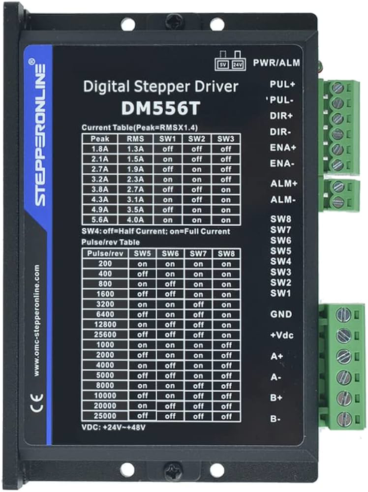
The DM556T is a high-performance digital stepper motor driver manufactured by Stepper Online. It is designed to provide precise control of stepper motors, supporting microstepping and offering robust protection features such as over-current, over-voltage, and short-circuit protection. This driver is suitable for a wide range of applications, including CNC machines, 3D printers, robotics, and other automation systems.
Explore Projects Built with DM556T
Use Cirkit Designer to design, explore, and prototype these projects online. Some projects support real-time simulation. Click "Open Project" to start designing instantly!
This circuit features an Arduino Mega 2560 microcontroller interfaced with a SIM800L GSM module, two fingerprint scanners, an I2C LCD display, an IR sensor, and a piezo buzzer. Power management is handled by a PowerBoost 1000 Basic Pad USB, a TP4056 charging module, and a Li-ion 18650 battery, with an option to use a Mini AC-DC 110V-230V to 5V 700mA module for direct power supply. The primary functionality appears to be a security system with GSM communication capabilities, biometric access control, and visual/audible feedback.
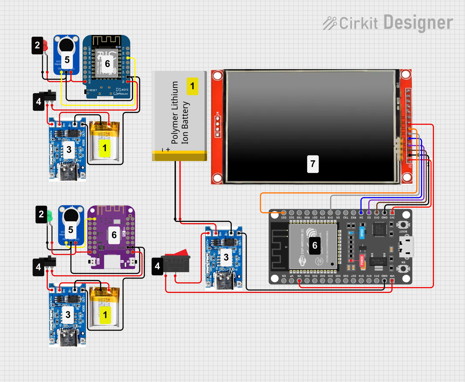
This is a portable audio-visual device featuring two Wemos microcontrollers for processing, Adafruit MAX4466 microphone amplifiers for audio input, and an LCD TFT screen for display. It includes power management with TP4056 modules and LiPo batteries, and user-controlled toggle and rocker switches.
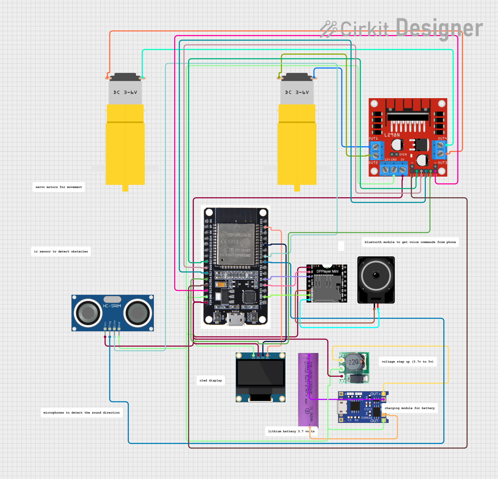
This circuit is a battery-powered system featuring an ESP32 microcontroller that controls an OLED display, a motor driver for two hobby motors, an ultrasonic sensor for distance measurement, and a DFPlayer Mini for audio output through a loudspeaker. The TP4056 module manages battery charging, and a step-up boost converter provides a stable 5V supply to the components.
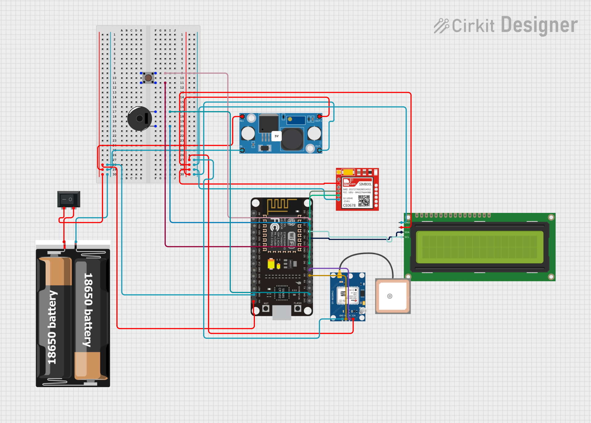
This circuit integrates an ESP8266 NodeMCU microcontroller with a SIM800L GSM module, a GPS NEO 6M module, and a 16x2 I2C LCD display for communication and location tracking. It also includes a pushbutton for user input, a piezo buzzer for audio alerts, and is powered by a 2x 18650 battery pack through an LM2596 step-down module.
Power Supply Connection: Connect the VCC and GND pins to a 20-50VDC power supply. Ensure the power supply can provide sufficient current for the stepper motor.
Motor Connection: Connect the A+, A-, B+, and B- pins to the corresponding phases of the stepper motor.
Control Signal Connection: Connect the PUL+, PUL-, DIR+, DIR-, ENA+, and ENA- pins to the appropriate control signals from your controller (e.g., Arduino, CNC controller).
Microstepping Configuration: Set the microstepping resolution using the DIP switches on the driver. Refer to the driver’s datasheet for the correct switch settings.
Enable Protection Features: Ensure that the driver is properly mounted and has adequate cooling to prevent overheating. The driver’s built-in protection features will help safeguard against over-current, over-voltage, and short-circuit conditions.
Important Considerations and Best Practices
Cooling: Ensure adequate ventilation or cooling for the driver to prevent overheating.
Wiring: Use appropriate gauge wires for power and motor connections to handle the current requirements.
Signal Integrity: Keep control signal wires short and shielded if possible to reduce noise and interference.
Power Supply: Use a stable and regulated power supply to avoid voltage fluctuations that could affect performance.
Troubleshooting and FAQs
Common Issues and Solutions
Motor Not Moving:
Check Power Supply: Ensure the power supply is connected and providing the correct voltage.
Verify Connections: Double-check all wiring connections, especially the motor and control signal connections.
Control Signals: Ensure the controller is sending the correct pulse and direction signals.
Overheating:
Cooling: Ensure the driver has adequate cooling and ventilation.
Current Setting: Verify that the current setting on the driver matches the motor’s rated current.
Erratic Motor Movement:
Signal Noise: Check for noise or interference in the control signal wires.
Microstepping Settings: Verify the microstepping settings on the DIP switches.
FAQs
Q: Can I use the DM556T with an Arduino UNO?
A: Yes, the DM556T can be controlled using an Arduino UNO. Below is an example code to control a stepper motor using the DM556T and Arduino UNO.
// Arduino UNO example code to control a stepper motor using DM556T

const int pulsePin = 9; // Pulse signal pin
const int dirPin = 8;   // Direction signal pin
const int enablePin = 7; // Enable signal pin (optional)

void setup() {
  pinMode(pulsePin, OUTPUT);
  pinMode(dirPin, OUTPUT);
  pinMode(enablePin, OUTPUT);

  digitalWrite(enablePin, LOW); // Enable the driver
  digitalWrite(dirPin, HIGH);   // Set direction
}

void loop() {
  digitalWrite(pulsePin, HIGH); // Generate a pulse
  delayMicroseconds(500);       // Pulse width
  digitalWrite(pulsePin, LOW);
  delayMicroseconds(500);       // Pulse interval
}
Q: How do I set the microstepping resolution?
A: The microstepping resolution is set using the DIP switches on the driver. Refer to the driver’s datasheet for the correct switch settings for your desired microstepping resolution.
Q: What should I do if the driver’s protection features are triggered?
A: If the driver’s protection features are triggered (e.g., over-current, over-voltage), first power off the system and check for wiring issues or component failures. Ensure the power supply voltage is within the specified range and that the motor current settings are correct.
By following this documentation, users can effectively utilize the DM556T digital stepper motor driver in their projects, ensuring reliable and precise control of stepper motors.


 Open Project in Cirkit Designer