Cirkit Designer
Your all-in-one circuit design IDE
Home /
Component Documentation
How to Use Proto: Examples, Pinouts, and Specs
Introduction
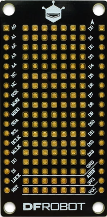
- The Proto, commonly referred to as a breadboard, is a reusable prototyping platform designed for building and testing electronic circuits without the need for soldering. It allows users to quickly assemble and modify circuits by inserting components and wires into its grid of interconnected holes.
- Common applications include:
- Rapid prototyping of electronic circuits
- Educational purposes for learning circuit design
- Testing and debugging circuit designs before final implementation
- Temporary setups for experimental projects
Explore Projects Built with Proto
Arduino-Based Temperature Monitoring System with RGB LED Feedback and I2C LCD Display
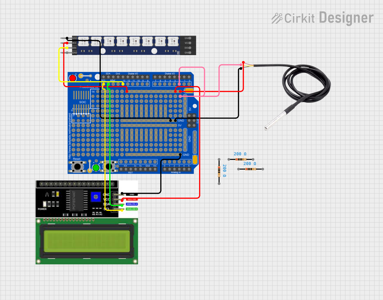
This circuit features an Adafruit Proto Shield R3 configured with a DS18B20 temperature sensor, a WS2812 RGB LED matrix, and an LCD I2C display. The microcontroller on the Proto Shield reads the temperature from the DS18B20 sensor and displays it on the LCD. It also controls the LED matrix to show random colors and indicates temperature status with onboard LEDs.
Arduino Pro Mini-Based Bluetooth and Camera-Controlled Motor System
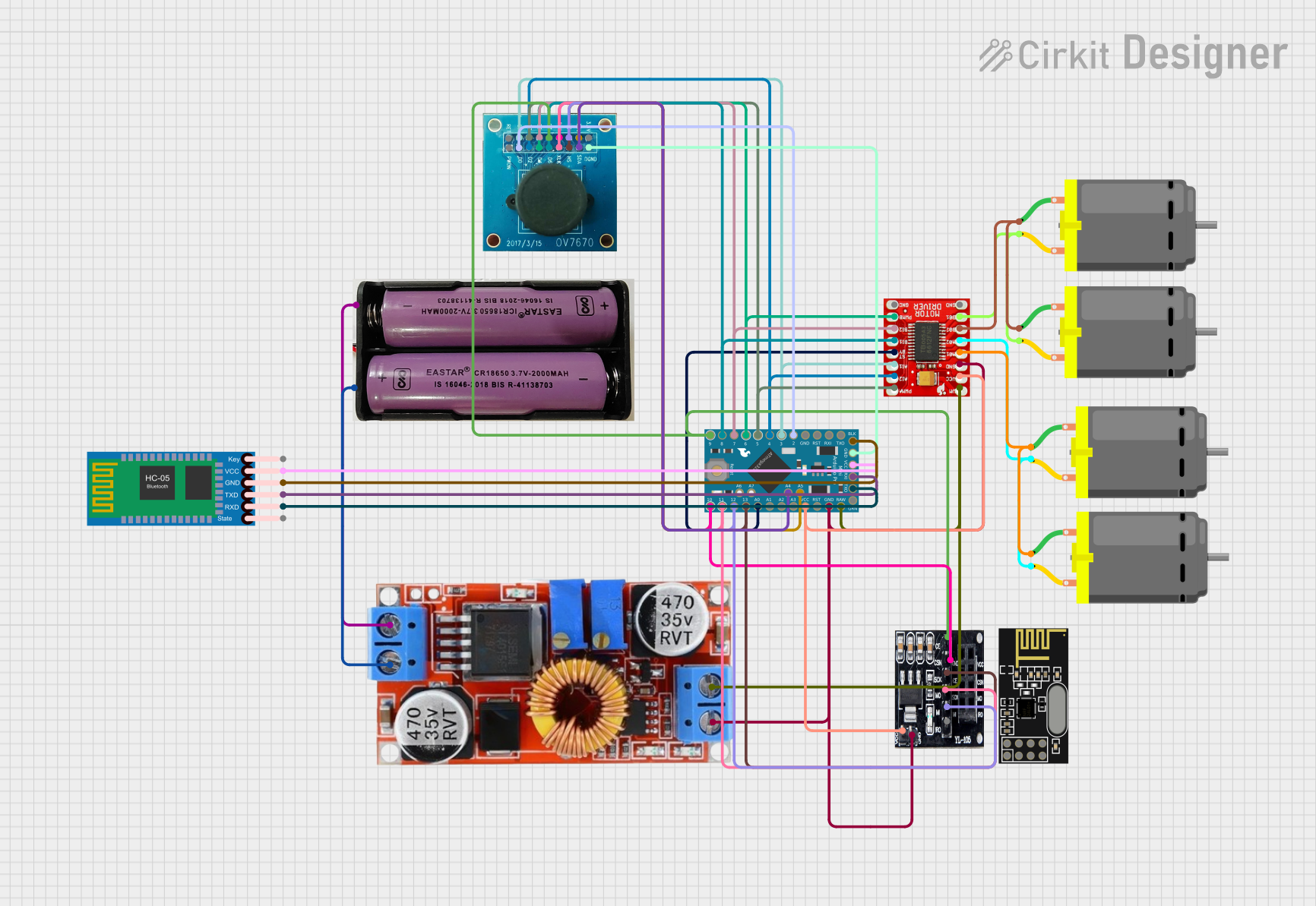
This circuit is a remote-controlled robotic system featuring an Arduino Pro Mini, a TB6612FNG motor driver, and an NRF24L01 wireless module. The Arduino controls four DC motors via the motor driver and communicates wirelessly using the NRF24L01 module, while an OV7670 camera module and an HC-05 Bluetooth module provide additional functionality.
Arduino Mega 2560-Based Reverse Vending Machine with GSM and Wi-Fi Connectivity
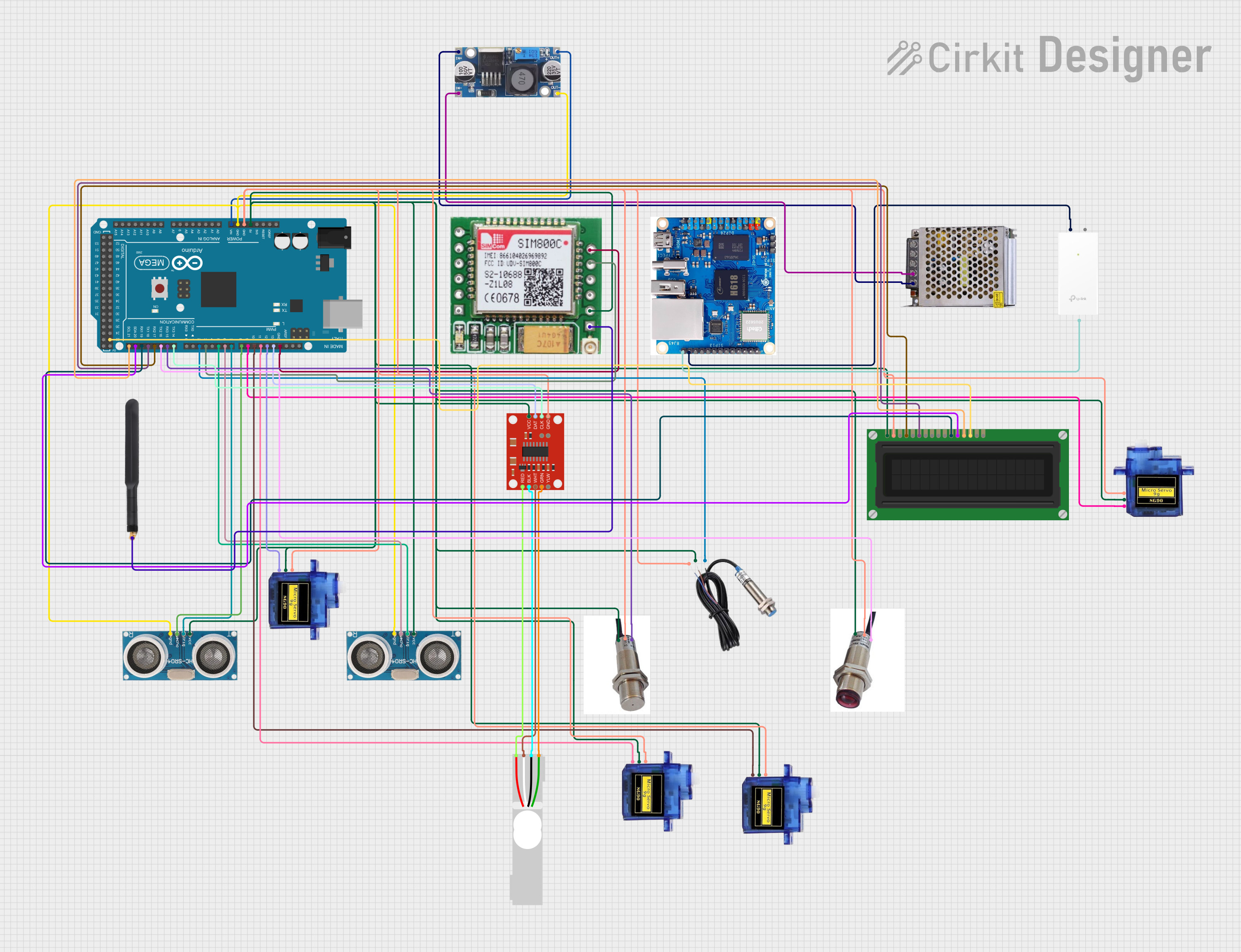
This circuit is a reverse vending machine for plastic bottles and cans, utilizing an Arduino Mega 2560 to interface with various sensors and actuators. It includes ultrasonic sensors for distance measurement, a load cell for weight measurement, micro servos for actuation, and a GSM module for communication. The system also features an LCD display for user interaction and uses inductive and photoelectric sensors for object detection.
Arduino-Controlled Motor System with Bluetooth Connectivity
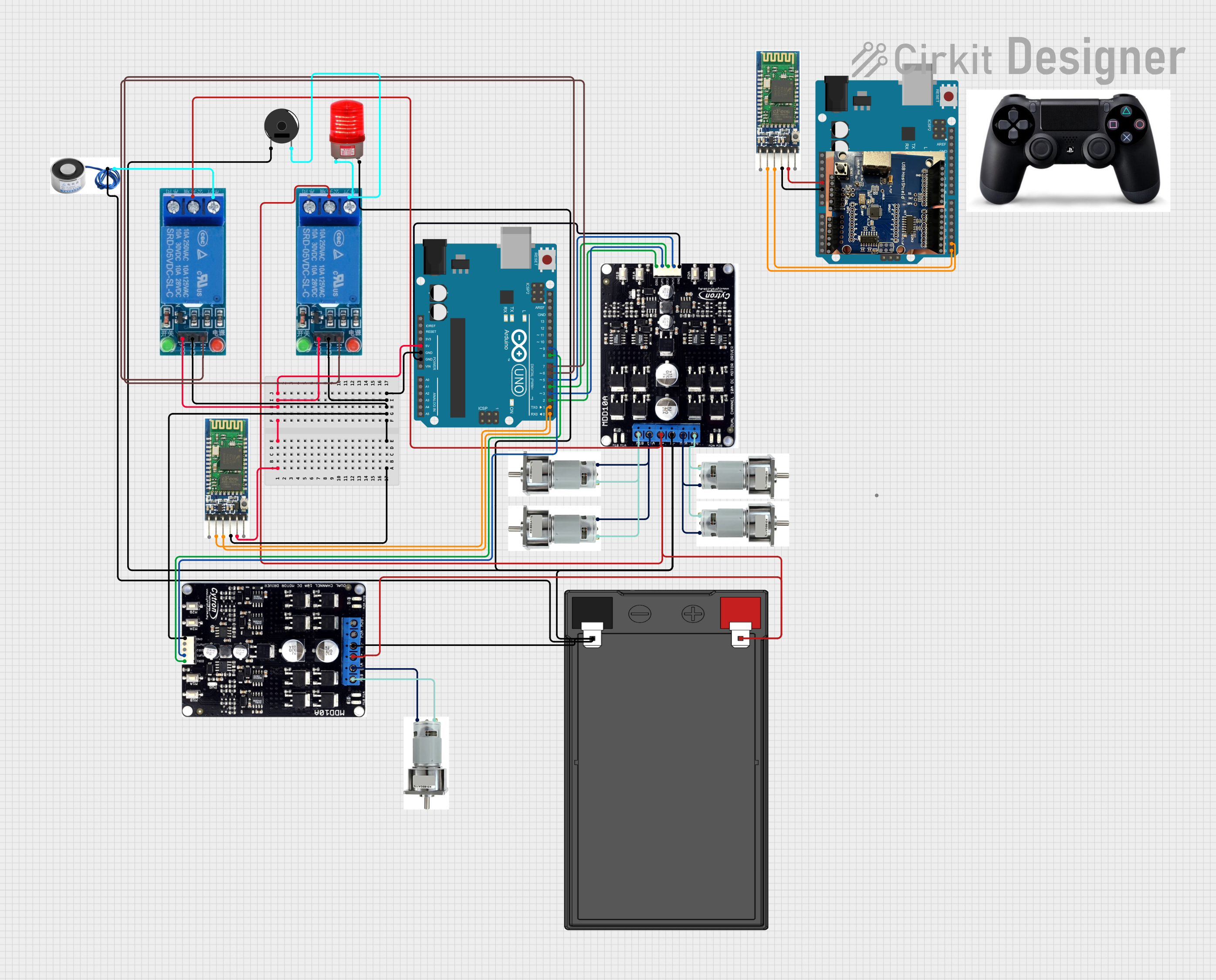
This is a motor control system with wireless communication capabilities, designed to operate multiple motors via Cytron motor drivers, controlled by Arduino UNOs. It includes relays for activating a light and buzzer, and uses Bluetooth for remote operation. The system's software is in the initial stages of development.
Explore Projects Built with Proto
Arduino-Based Temperature Monitoring System with RGB LED Feedback and I2C LCD Display
This circuit features an Adafruit Proto Shield R3 configured with a DS18B20 temperature sensor, a WS2812 RGB LED matrix, and an LCD I2C display. The microcontroller on the Proto Shield reads the temperature from the DS18B20 sensor and displays it on the LCD. It also controls the LED matrix to show random colors and indicates temperature status with onboard LEDs.
Arduino Pro Mini-Based Bluetooth and Camera-Controlled Motor System
This circuit is a remote-controlled robotic system featuring an Arduino Pro Mini, a TB6612FNG motor driver, and an NRF24L01 wireless module. The Arduino controls four DC motors via the motor driver and communicates wirelessly using the NRF24L01 module, while an OV7670 camera module and an HC-05 Bluetooth module provide additional functionality.
Arduino Mega 2560-Based Reverse Vending Machine with GSM and Wi-Fi Connectivity
This circuit is a reverse vending machine for plastic bottles and cans, utilizing an Arduino Mega 2560 to interface with various sensors and actuators. It includes ultrasonic sensors for distance measurement, a load cell for weight measurement, micro servos for actuation, and a GSM module for communication. The system also features an LCD display for user interaction and uses inductive and photoelectric sensors for object detection.
Arduino-Controlled Motor System with Bluetooth Connectivity
This is a motor control system with wireless communication capabilities, designed to operate multiple motors via Cytron motor drivers, controlled by Arduino UNOs. It includes relays for activating a light and buzzer, and uses Bluetooth for remote operation. The system's software is in the initial stages of development.
Technical Specifications
- Material: ABS plastic body with nickel-plated phosphor bronze contacts
- Dimensions: Typically 170mm x 55mm x 10mm (varies by model)
- Hole Pitch: 2.54mm (0.1 inch)
- Power Rails: Dual power rails for easy power distribution
- Terminal Strips: 630 tie-points (varies by model)
- Voltage Rating: Up to 36V DC
- Current Rating: Up to 2A per contact
- Compatibility: Supports standard through-hole components and jumper wires
Pin Configuration and Descriptions
The Proto does not have traditional pins but consists of interconnected rows and columns. Below is a description of its layout:
| Section | Description |
|---|---|
| Terminal Strips | Central area with rows of interconnected holes for placing components. |
| Power Rails | Horizontal rows on the top and bottom edges for distributing power (VCC/GND). |
| Tie-Points | Individual holes where components or wires are inserted. |
Usage Instructions
Setting Up the Proto:
- Place the Proto on a flat, stable surface.
- Connect a power supply to the power rails (e.g., 5V and GND for most circuits).
- Use jumper wires to distribute power to the desired rows.
Building a Circuit:
- Insert components (e.g., resistors, LEDs, ICs) into the terminal strip holes.
- Ensure that components are placed in separate rows unless they need to be electrically connected.
- Use jumper wires to connect different parts of the circuit.
Connecting to an Arduino UNO:
- Use jumper wires to connect the Arduino's pins to the Proto.
- Example: Connect the Arduino's 5V and GND pins to the Proto's power rails.
Example Circuit: Blinking LED with Arduino UNO
// Connect the LED's anode (long leg) to pin 13 on the Arduino via a 220-ohm resistor.
// Connect the LED's cathode (short leg) to the Proto's GND rail.

void setup() {
  pinMode(13, OUTPUT); // Set pin 13 as an output pin
}

void loop() {
  digitalWrite(13, HIGH); // Turn the LED on
  delay(1000);            // Wait for 1 second
  digitalWrite(13, LOW);  // Turn the LED off
  delay(1000);            // Wait for 1 second
}
Best Practices:
- Avoid inserting wires or components with excessively thick leads, as this may damage the contacts.
- Keep the Proto clean and free of debris to ensure reliable connections.
- Use color-coded jumper wires for better organization (e.g., red for VCC, black for GND).
Troubleshooting and FAQs
Common Issues
Loose Connections:
- Cause: Worn-out contacts or improperly inserted components.
- Solution: Ensure components are fully inserted into the holes. Replace the Proto if contacts are damaged.
Short Circuits:
- Cause: Components or wires unintentionally touching.
- Solution: Double-check connections and ensure no exposed wires are touching.
Power Distribution Problems:
- Cause: Incorrectly connected power rails.
- Solution: Verify that the power supply is correctly connected to the Proto's power rails.
FAQs
Can I use the Proto for high-power circuits?
- No, the Proto is designed for low-power circuits (up to 36V DC and 2A). For high-power applications, use appropriate connectors and soldered connections.
How do I clean the Proto?
- Use a soft brush or compressed air to remove dust and debris. Avoid using liquids.
Can I connect multiple Protos together?
- Yes, many Protos have interlocking edges that allow you to connect multiple boards for larger projects.
By following this documentation, you can effectively use the Proto for prototyping and testing your electronic circuits.