Cirkit Designer Logo
Cirkit Designer
Your all-in-one circuit design IDE
Home / 
Component Documentation

How to Use Adafruit PiTFT 2.4 inch HAT: Examples, Pinouts, and Specs

Image of Adafruit PiTFT 2.4 inch HAT
Cirkit Designer LogoDesign with Adafruit PiTFT 2.4 inch HAT in Cirkit Designer

Introduction

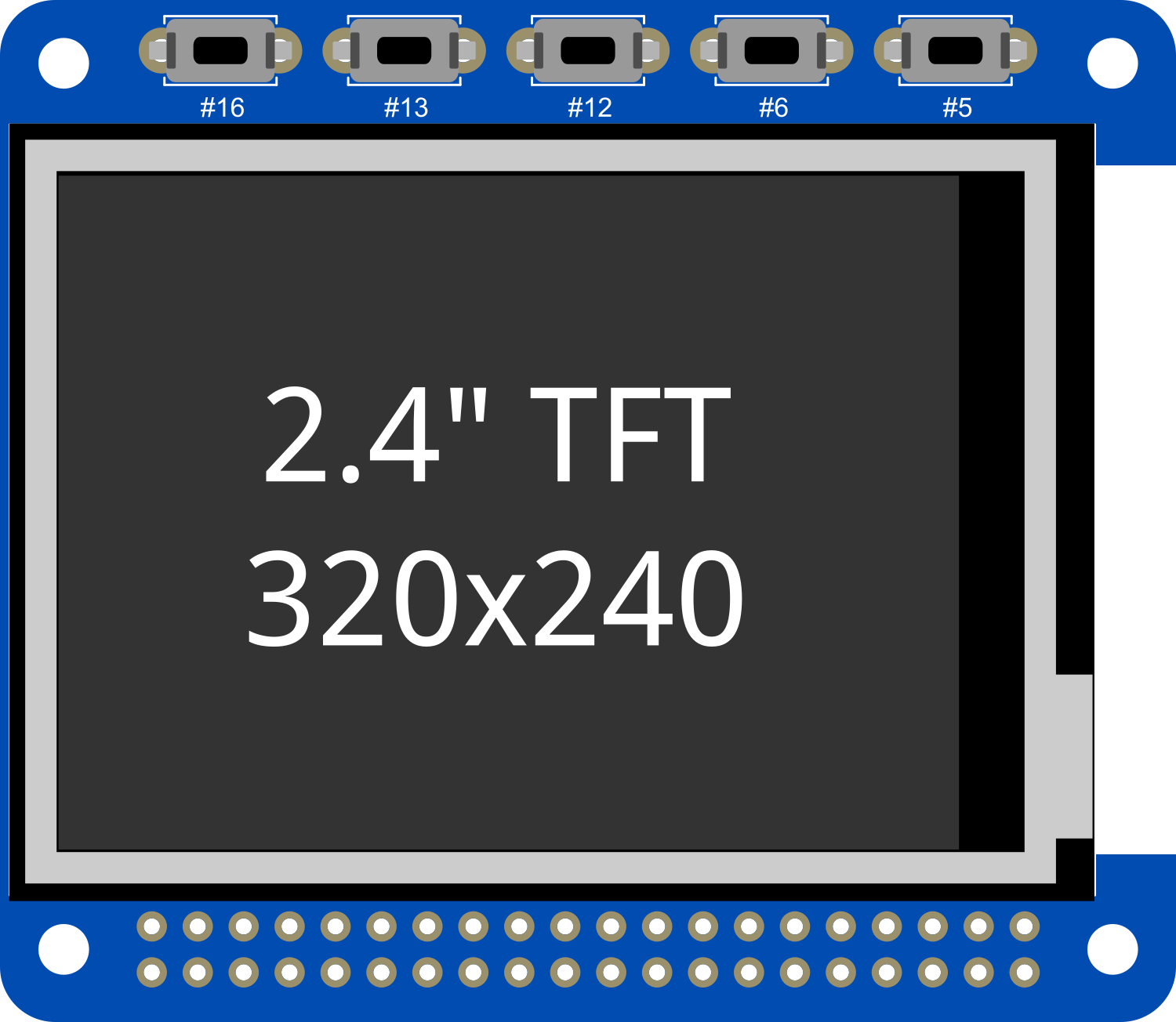
The Adafruit PiTFT 2.4 inch HAT is a versatile and compact display module specifically designed for the Raspberry Pi. This HAT (Hardware Attached on Top) features a 2.4-inch TFT screen with resistive touch control, offering a convenient interface for projects that require a graphical display and user input. It is compatible with all Raspberry Pi models equipped with a 40-pin GPIO header, making it a flexible option for a wide range of applications, from handheld devices to control panels for DIY projects.

Explore Projects Built with Adafruit PiTFT 2.4 inch HAT

Use Cirkit Designer to design, explore, and prototype these projects online. Some projects support real-time simulation. Click "Open Project" to start designing instantly!
Raspberry Pi 4B-Based Multi-Sensor Interface Hub with GPS and GSM
Image of Rocket: A project utilizing Adafruit PiTFT 2.4 inch HAT in a practical application
This circuit features a Raspberry Pi 4B interfaced with an IMX296 color global shutter camera, a Neo 6M GPS module, an Adafruit BMP388 barometric pressure sensor, an MPU-6050 accelerometer/gyroscope, and a Sim800l GSM module for cellular connectivity. Power management is handled by an MT3608 boost converter, which steps up the voltage from a Lipo battery, with a resettable fuse PTC and a 1N4007 diode for protection. The Adafruit Perma-Proto HAT is used for organizing connections and interfacing the sensors and modules with the Raspberry Pi via I2C and GPIO pins.
Cirkit Designer LogoOpen Project in Cirkit Designer
Raspberry Pi Pico and OV7670 Camera-Based Robotic System with TFT Display
Image of REF Speed Bot V3 CKT: A project utilizing Adafruit PiTFT 2.4 inch HAT in a practical application
This circuit features two Raspberry Pi Pico microcontrollers interfacing with various peripherals including an OV7670 camera module, a TFT display, and an OLED display. It also includes a multiplexer and a motor driver to control two planetary gearbox motors, powered by a battery and regulated through buck converters. The setup is designed for image capture, display, and motor control applications.
Cirkit Designer LogoOpen Project in Cirkit Designer
Raspberry Pi 5 Smart Weather Station with GPS and AI Integration
Image of Senior Design: A project utilizing Adafruit PiTFT 2.4 inch HAT in a practical application
This circuit integrates a Raspberry Pi 5 with various peripherals including an 8MP 3D stereo camera, an AI Hat, a BMP388 sensor, a 16x2 I2C LCD, and an Adafruit Ultimate GPS module. The Raspberry Pi serves as the central processing unit, interfacing with the camera for image capture, the AI Hat for AI processing, the BMP388 for environmental sensing, the LCD for display, and the GPS module for location tracking, with a USB Serial TTL for serial communication.
Cirkit Designer LogoOpen Project in Cirkit Designer
Raspberry Pi 4B-Based Current Monitoring System with I2C OLED Display
Image of Virtual Energy Monitoring Circuit: A project utilizing Adafruit PiTFT 2.4 inch HAT in a practical application
This circuit features a Raspberry Pi 4B as the central processing unit, interfaced with an Adafruit ADS1115 16-bit I2C ADC for analog-to-digital conversion and a 0.96" OLED display for visual output. The ADS1115 is connected to a current sensor for measuring electrical current, with the sensor's output and burden pins connected to the ADC's analog input channels. The Raspberry Pi communicates with both the ADC and the OLED display over the I2C bus, using its GPIO2 and GPIO3 pins for data (SDA) and clock (SCL) lines, respectively.
Cirkit Designer LogoOpen Project in Cirkit Designer

Explore Projects Built with Adafruit PiTFT 2.4 inch HAT

Use Cirkit Designer to design, explore, and prototype these projects online. Some projects support real-time simulation. Click "Open Project" to start designing instantly!
Image of Rocket: A project utilizing Adafruit PiTFT 2.4 inch HAT in a practical application
Raspberry Pi 4B-Based Multi-Sensor Interface Hub with GPS and GSM
This circuit features a Raspberry Pi 4B interfaced with an IMX296 color global shutter camera, a Neo 6M GPS module, an Adafruit BMP388 barometric pressure sensor, an MPU-6050 accelerometer/gyroscope, and a Sim800l GSM module for cellular connectivity. Power management is handled by an MT3608 boost converter, which steps up the voltage from a Lipo battery, with a resettable fuse PTC and a 1N4007 diode for protection. The Adafruit Perma-Proto HAT is used for organizing connections and interfacing the sensors and modules with the Raspberry Pi via I2C and GPIO pins.
Cirkit Designer LogoOpen Project in Cirkit Designer
Image of REF Speed Bot V3 CKT: A project utilizing Adafruit PiTFT 2.4 inch HAT in a practical application
Raspberry Pi Pico and OV7670 Camera-Based Robotic System with TFT Display
This circuit features two Raspberry Pi Pico microcontrollers interfacing with various peripherals including an OV7670 camera module, a TFT display, and an OLED display. It also includes a multiplexer and a motor driver to control two planetary gearbox motors, powered by a battery and regulated through buck converters. The setup is designed for image capture, display, and motor control applications.
Cirkit Designer LogoOpen Project in Cirkit Designer
Image of Senior Design: A project utilizing Adafruit PiTFT 2.4 inch HAT in a practical application
Raspberry Pi 5 Smart Weather Station with GPS and AI Integration
This circuit integrates a Raspberry Pi 5 with various peripherals including an 8MP 3D stereo camera, an AI Hat, a BMP388 sensor, a 16x2 I2C LCD, and an Adafruit Ultimate GPS module. The Raspberry Pi serves as the central processing unit, interfacing with the camera for image capture, the AI Hat for AI processing, the BMP388 for environmental sensing, the LCD for display, and the GPS module for location tracking, with a USB Serial TTL for serial communication.
Cirkit Designer LogoOpen Project in Cirkit Designer
Image of Virtual Energy Monitoring Circuit: A project utilizing Adafruit PiTFT 2.4 inch HAT in a practical application
Raspberry Pi 4B-Based Current Monitoring System with I2C OLED Display
This circuit features a Raspberry Pi 4B as the central processing unit, interfaced with an Adafruit ADS1115 16-bit I2C ADC for analog-to-digital conversion and a 0.96" OLED display for visual output. The ADS1115 is connected to a current sensor for measuring electrical current, with the sensor's output and burden pins connected to the ADC's analog input channels. The Raspberry Pi communicates with both the ADC and the OLED display over the I2C bus, using its GPIO2 and GPIO3 pins for data (SDA) and clock (SCL) lines, respectively.
Cirkit Designer LogoOpen Project in Cirkit Designer

Common Applications and Use Cases

  • DIY portable gaming consoles
  • Home automation control panels
  • Interactive project displays
  • Development and prototyping of user interfaces
  • Educational tools for learning programming and electronics

Technical Specifications

Key Technical Details

  • Display Size: 2.4 inches diagonal
  • LCD Type: TFT
  • Resolution: 320x240 pixels
  • Touch Control: Resistive touch overlay
  • Interface: SPI
  • Backlight: LED
  • Operating Voltage: 3.3V (5V tolerant)
  • Current Draw: 100mA (typical usage)

Pin Configuration and Descriptions

Pin Number Name Description
1 3V3 3.3V Power Supply
2 5V 5V Power Supply
6 GND Ground
18 BCM24 Display data/command select
19 MOSI SPI data input to TFT
21 MISO SPI data output from TFT (not used)
22 BCM25 Touchscreen interrupt (not used by default)
23 SCLK SPI clock input to TFT
24 CE0 SPI chip select for TFT
26 CE1 SPI chip select for touch controller

Usage Instructions

How to Use the Component in a Circuit

  1. Mounting the HAT: Carefully align the PiTFT HAT's GPIO connector with the Raspberry Pi's GPIO header and press down to connect.
  2. Powering the PiTFT: The PiTFT HAT draws power directly from the Raspberry Pi's GPIO pins. No additional power supply is needed.
  3. Software Configuration: Before using the display, you'll need to install and configure the necessary drivers and software on your Raspberry Pi.

Important Considerations and Best Practices

  • Static Sensitivity: As with all electronic components, take precautions against electrostatic discharge (ESD) when handling the PiTFT.
  • Power Supply: Ensure that your Raspberry Pi has an adequate power supply, especially if you're connecting additional peripherals.
  • Display Protection: The resistive touchscreen is sensitive to scratches and pressure. Consider using a stylus or applying a screen protector.

Troubleshooting and FAQs

Common Issues Users Might Face

  • Display Not Turning On: Check the connection between the PiTFT and the Raspberry Pi. Ensure that the GPIO pins are properly aligned and seated.
  • Touchscreen Not Responsive: Verify that the touchscreen drivers are correctly installed and that the SPI interface is enabled on your Raspberry Pi.
  • Image Quality Issues: If the display appears washed out or has poor contrast, adjust the settings in the software configuration for better image quality.

Solutions and Tips for Troubleshooting

  • Recheck Connections: Loose or incorrect connections are often the cause of issues. Double-check all connections.
  • Review Software Setup: Ensure that you've followed all the steps in the software installation guide provided by Adafruit.
  • Update Raspberry Pi: Make sure your Raspberry Pi is running the latest version of its operating system and all packages are up to date.

FAQs

Q: Can I use the PiTFT with a Raspberry Pi Zero? A: Yes, the PiTFT can be used with a Raspberry Pi Zero, but you may need an adapter or soldering to connect the 40-pin GPIO header.

Q: Is the touchscreen capacitive or resistive? A: The touchscreen is resistive, which means it responds to pressure and can be used with a stylus or finger.

Q: How do I calibrate the touchscreen? A: Calibration can be done through the adafruit-pitft-helper script provided by Adafruit, which will guide you through the calibration process.

For further assistance, refer to the Adafruit forums or the detailed guides available on the Adafruit website.