How to Use Arduino nano 33 BLE sense Rev 2: Examples, Pinouts, and Specs
Introduction
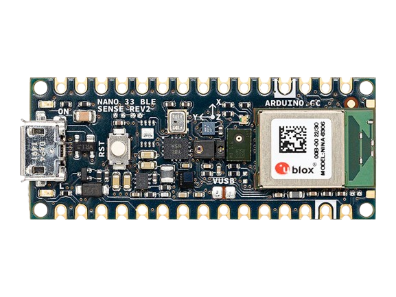
The Arduino Nano 33 BLE Sense Rev 2 is a compact and versatile microcontroller board designed for advanced IoT and wearable applications. Manufactured by Arduino, this board features Bluetooth Low Energy (BLE) capabilities, a powerful ARM Cortex-M4 processor, and a suite of integrated sensors. Its small form factor and robust features make it ideal for projects requiring wireless communication, environmental sensing, and machine learning.
Explore Projects Built with Arduino nano 33 BLE sense Rev 2
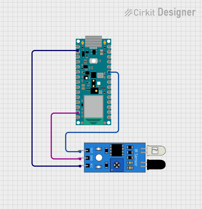
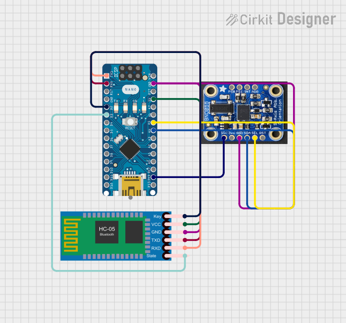
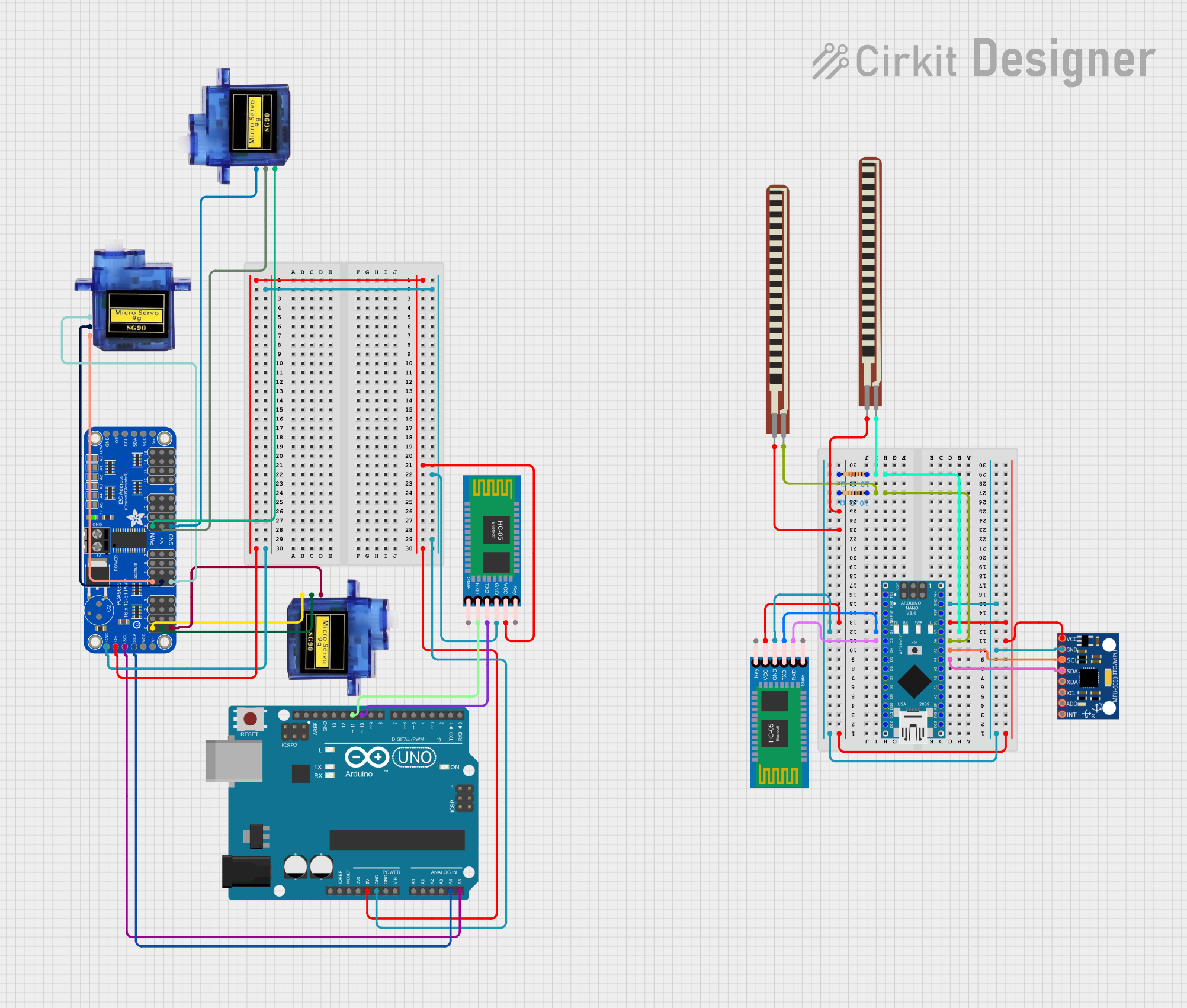
Explore Projects Built with Arduino nano 33 BLE sense Rev 2
Common Applications and Use Cases
- IoT (Internet of Things) devices and smart home automation
- Wearable technology and fitness trackers
- Environmental monitoring (e.g., temperature, humidity, air quality)
- Machine learning and edge computing
- Robotics and sensor-based projects
Technical Specifications
The following table outlines the key technical details of the Arduino Nano 33 BLE Sense Rev 2:
| Specification | Details |
|---|---|
| Processor | ARM Cortex-M4 32-bit processor with FPU running at 64 MHz |
| Bluetooth | Bluetooth Low Energy (BLE) 5.0 |
| Flash Memory | 256 KB |
| SRAM | 256 KB |
| Operating Voltage | 3.3V |
| Input Voltage | 5V (via USB) or 3.3V (via VIN pin) |
| Digital I/O Pins | 14 |
| PWM Pins | 8 |
| Analog Input Pins | 8 |
| Communication Protocols | UART, I2C, SPI |
| Integrated Sensors | Temperature, humidity, barometric pressure, gesture, proximity, and more |
| Dimensions | 45 x 18 mm |
Pin Configuration and Descriptions
The Arduino Nano 33 BLE Sense Rev 2 has a total of 30 pins. Below is a summary of the pin configuration:
| Pin | Name | Description |
|---|---|---|
| 1 | VIN | Input voltage to the board (3.3V to 5V) |
| 2 | GND | Ground pin |
| 3 | 3.3V | Regulated 3.3V output |
| 4-11 | D0-D7 | Digital I/O pins (D3, D5, D6, and D9 support PWM) |
| 12-13 | RX, TX | UART communication pins |
| 14-21 | A0-A7 | Analog input pins |
| 22-23 | SDA, SCL | I2C communication pins |
| 24-25 | MOSI, MISO | SPI communication pins |
| 26 | SCK | SPI clock pin |
| 27 | RST | Reset pin |
| 28-30 | NC | Not connected |
Usage Instructions
How to Use the Component in a Circuit
Powering the Board:
- Connect the board to a computer or power source using a USB cable (5V input).
- Alternatively, supply 3.3V to the VIN pin for external power.
Programming the Board:
- Install the Arduino IDE and add the "Arduino Mbed OS Nano Boards" package via the Board Manager.
- Select "Arduino Nano 33 BLE Sense" as the board in the IDE.
- Write and upload your code using the USB connection.
Connecting Sensors and Actuators:
- Use the digital and analog pins to connect external components like LEDs, motors, or additional sensors.
- For I2C devices, connect them to the SDA and SCL pins.
- For SPI devices, use the MOSI, MISO, and SCK pins.
Using Built-in Sensors:
- The board includes several onboard sensors (e.g., temperature, humidity, and gesture sensors).
- Use the appropriate libraries (e.g.,
Arduino_LSM9DS1for motion sensing) to interface with these sensors.
Important Considerations and Best Practices
- Voltage Levels: Ensure all connected components operate at 3.3V logic levels to avoid damaging the board.
- BLE Communication: Use the
ArduinoBLElibrary to implement Bluetooth Low Energy functionality. - Heat Management: Avoid placing the board in high-temperature environments to prevent overheating.
- Firmware Updates: Regularly update the board's firmware for optimal performance and compatibility.
Example Code: Reading Temperature and Humidity
The following example demonstrates how to read data from the onboard temperature and humidity sensor:
#include <Arduino_HTS221.h> // Include the library for the HTS221 sensor

void setup() {
  Serial.begin(9600); // Initialize serial communication at 9600 baud
  while (!Serial);    // Wait for the serial monitor to open

  if (!HTS.begin()) {
    // Check if the sensor is initialized successfully
    Serial.println("Failed to initialize HTS221 sensor!");
    while (1); // Halt execution if initialization fails
  }
  Serial.println("HTS221 sensor initialized successfully.");
}

void loop() {
  float temperature = HTS.readTemperature(); // Read temperature in Celsius
  float humidity = HTS.readHumidity();       // Read relative humidity in %

  // Print the sensor readings to the serial monitor
  Serial.print("Temperature: ");
  Serial.print(temperature);
  Serial.println(" °C");

  Serial.print("Humidity: ");
  Serial.print(humidity);
  Serial.println(" %");

  delay(1000); // Wait for 1 second before the next reading
}
Troubleshooting and FAQs
Common Issues and Solutions
Board Not Detected by Arduino IDE:
- Ensure the correct board and port are selected in the IDE.
- Check the USB cable and connection. Use a data-capable USB cable, not a charge-only cable.
BLE Not Working:
- Verify that the
ArduinoBLElibrary is installed and included in your sketch. - Ensure the BLE device is not already connected to another device.
- Verify that the
Sensors Not Responding:
- Confirm that the appropriate sensor library is installed and initialized in the code.
- Check for loose connections or damaged components.
Power Issues:
- Ensure the input voltage is within the specified range (3.3V to 5V).
- Avoid powering high-current devices directly from the board.
FAQs
Q: Can I use the Arduino Nano 33 BLE Sense Rev 2 with a 5V sensor?
A: No, the board operates at 3.3V logic levels. Use a level shifter to interface with 5V sensors.
Q: How do I update the firmware?
A: Use the Arduino IDE or the Arduino CLI to update the firmware. Follow the instructions provided in the Arduino support documentation.
Q: Is the board compatible with Arduino shields?
A: The Nano 33 BLE Sense Rev 2 is not directly compatible with standard Arduino shields due to its smaller form factor. However, you can use breakout boards or custom wiring to connect shields.
Q: Can I use the board for machine learning applications?
A: Yes, the board supports TensorFlow Lite for Microcontrollers, enabling on-device machine learning.