How to Use 24v 100a Motor Speed Controller Pwm Reverse Control Switch With Led Display - Motor Controller: Examples, Pinouts, and Specs
Introduction
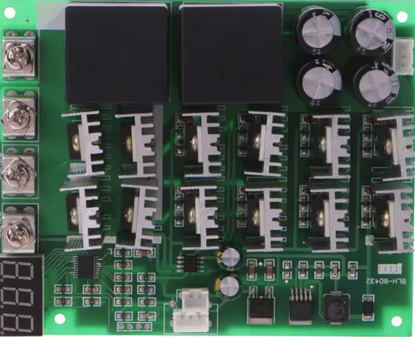
The 24V 100A Motor Speed Controller PWM Reverse Control Switch with LED Display (Manufacturer Part ID: 01-E) is a versatile and robust motor controller designed for 24V DC motors. It utilizes Pulse Width Modulation (PWM) technology to provide precise speed control while maintaining high efficiency. This controller is capable of handling up to 100A of current, making it suitable for high-power motor applications. Additionally, it features a reverse control switch for changing motor direction and an LED display for real-time speed monitoring.
Explore Projects Built with 24v 100a Motor Speed Controller Pwm Reverse Control Switch With Led Display - Motor Controller
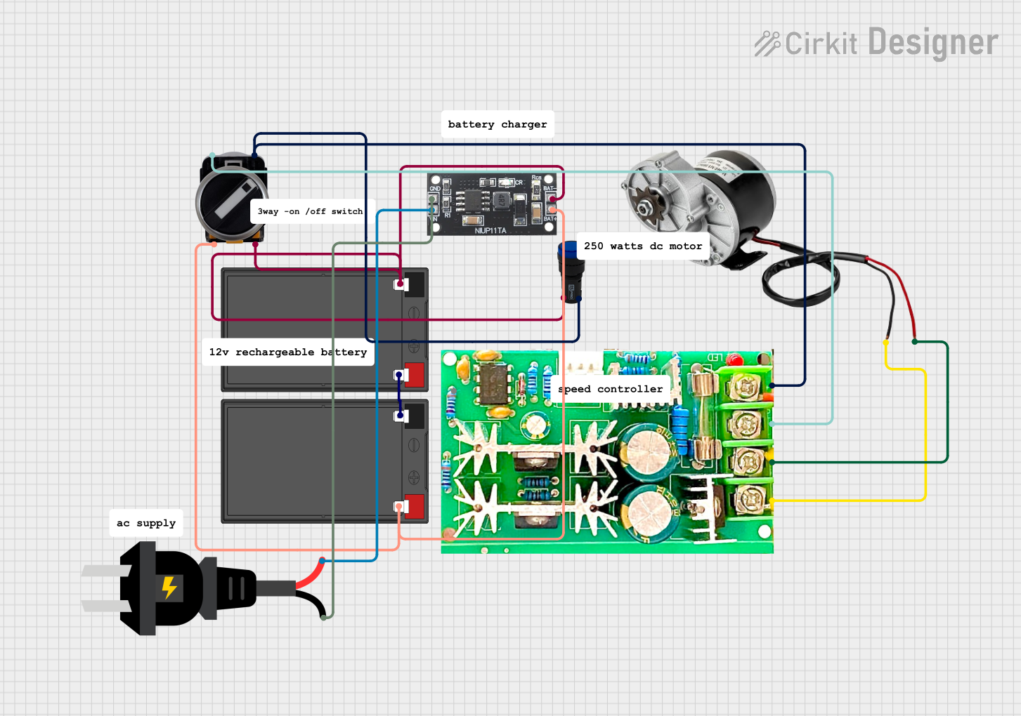


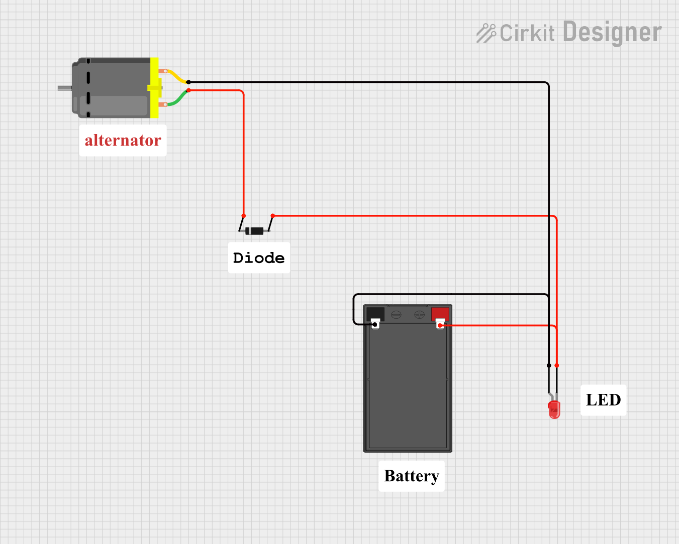
Explore Projects Built with 24v 100a Motor Speed Controller Pwm Reverse Control Switch With Led Display - Motor Controller
Common Applications and Use Cases
- Electric vehicles (e.g., scooters, bikes, and carts)
- Industrial conveyor belts
- Robotics and automation systems
- High-power fans and pumps
- DIY motorized projects
Technical Specifications
Below are the key technical details of the motor controller:
| Parameter | Specification |
|---|---|
| Input Voltage | 24V DC |
| Maximum Current | 100A |
| Control Method | PWM (Pulse Width Modulation) |
| Speed Adjustment Range | 0% to 100% |
| Reverse Control | Yes (via toggle switch) |
| Display | LED display for speed level |
| Operating Temperature | -10°C to 50°C |
| Dimensions | 150mm x 80mm x 50mm |
| Weight | 400g |
Pin Configuration and Descriptions
The motor controller has the following input/output terminals:
| Pin/Terminal | Description |
|---|---|
| VIN+ | Positive input terminal for 24V DC power supply. |
| VIN- | Negative input terminal for 24V DC power supply. |
| M+ | Positive terminal for the motor connection. |
| M- | Negative terminal for the motor connection. |
| Reverse Switch | Toggle switch for reversing motor direction. |
| Speed Knob | Rotary potentiometer for adjusting motor speed (0% to 100%). |
| LED Display | Displays the current speed setting as a percentage. |
Usage Instructions
How to Use the Component in a Circuit
Power Supply Connection:
- Connect a 24V DC power supply to the
VIN+andVIN-terminals. Ensure the power supply can handle the required current (up to 100A). - Use appropriately rated wires to handle high current without overheating.
- Connect a 24V DC power supply to the
Motor Connection:
- Connect the motor's positive terminal to
M+and the negative terminal toM-. - Double-check the connections to avoid reversing polarity, which could damage the motor or controller.
- Connect the motor's positive terminal to
Speed Adjustment:
- Use the rotary potentiometer (speed knob) to adjust the motor speed. The LED display will show the speed as a percentage (0% to 100%).
Direction Control:
- Use the reverse toggle switch to change the motor's direction. Ensure the motor is stopped before toggling the switch to prevent damage.
Testing:
- Power on the system and gradually increase the speed using the potentiometer. Monitor the LED display for feedback.
Important Considerations and Best Practices
- Current Handling: Ensure the motor's current draw does not exceed 100A. Use a fuse or circuit breaker for added protection.
- Heat Dissipation: The controller may generate heat during operation. Install it in a well-ventilated area or use a heat sink if necessary.
- Wiring: Use thick, high-quality wires to handle the high current. Poor wiring can lead to voltage drops and overheating.
- Polarity: Double-check all connections to avoid reversing polarity, which can damage the controller or motor.
- Safety: Disconnect the power supply before making any changes to the wiring or connections.
Arduino UNO Integration Example
This motor controller can be integrated with an Arduino UNO for automated speed control. Below is an example code snippet:
// Arduino code to control the 24V 100A Motor Speed Controller
// using a PWM signal from pin 9 and a digital pin for direction control.

const int pwmPin = 9;       // PWM output pin for speed control
const int dirPin = 8;       // Digital output pin for direction control

void setup() {
  pinMode(pwmPin, OUTPUT);  // Set PWM pin as output
  pinMode(dirPin, OUTPUT);  // Set direction pin as output

  // Initialize motor direction to forward
  digitalWrite(dirPin, LOW);
}

void loop() {
  // Example: Gradually increase motor speed from 0% to 100%
  for (int speed = 0; speed <= 255; speed++) {
    analogWrite(pwmPin, speed);  // Send PWM signal to control speed
    delay(20);                   // Wait 20ms before increasing speed
  }

  // Reverse motor direction
  digitalWrite(dirPin, HIGH);    // Set direction to reverse
  delay(1000);                   // Wait for 1 second

  // Example: Gradually decrease motor speed from 100% to 0%
  for (int speed = 255; speed >= 0; speed--) {
    analogWrite(pwmPin, speed);  // Send PWM signal to control speed
    delay(20);                   // Wait 20ms before decreasing speed
  }

  // Set direction back to forward
  digitalWrite(dirPin, LOW);
  delay(1000);                   // Wait for 1 second
}
Troubleshooting and FAQs
Common Issues and Solutions
Motor Does Not Start:
- Cause: Incorrect wiring or insufficient power supply.
- Solution: Verify all connections and ensure the power supply provides 24V and sufficient current.
LED Display Not Working:
- Cause: Faulty connection or damaged display.
- Solution: Check the wiring to the display and ensure it is securely connected.
Motor Runs in the Wrong Direction:
- Cause: Reverse toggle switch is in the wrong position.
- Solution: Toggle the reverse switch to change the direction.
Controller Overheats:
- Cause: Prolonged operation at high current without proper ventilation.
- Solution: Install the controller in a well-ventilated area or use a heat sink.
PWM Signal Not Detected (Arduino Integration):
- Cause: Incorrect pin configuration or damaged Arduino pin.
- Solution: Verify the Arduino code and connections. Ensure the correct pins are used.
FAQs
Q: Can this controller be used with a 12V motor?
- A: No, this controller is designed specifically for 24V DC motors.
Q: What type of fuse should I use for protection?
- A: Use a 100A fuse rated for DC circuits to protect the controller and motor.
Q: Can I use this controller for brushless motors?
- A: No, this controller is designed for brushed DC motors only.
Q: Is the reverse switch safe to use while the motor is running?
- A: It is recommended to stop the motor before toggling the reverse switch to avoid damage.