How to Use SSD1306 I2C OLED Display: Examples, Pinouts, and Specs
Introduction
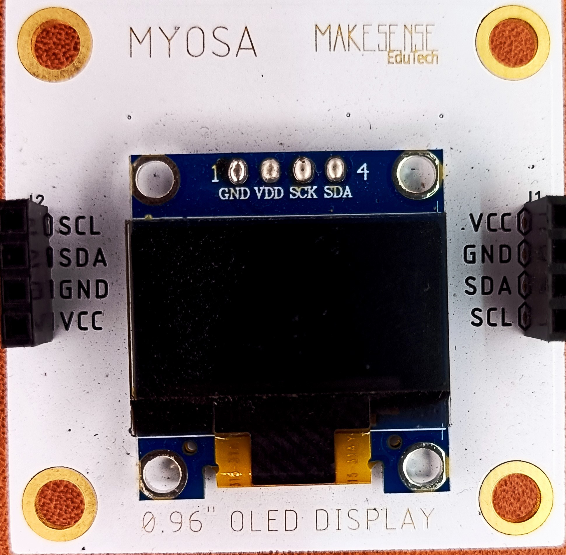
The SSD1306 I2C OLED Display, manufactured by MYOSA, is a small, low-power display module that uses the I2C communication protocol. It is commonly used for displaying text and graphics in embedded systems and microcontroller projects. This versatile display is ideal for applications where space and power consumption are critical, such as wearable devices, portable electronics, and various DIY projects.
Explore Projects Built with SSD1306 I2C OLED Display


Explore Projects Built with SSD1306 I2C OLED Display
Technical Specifications
Key Technical Details
| Parameter | Value |
|---|---|
| Display Type | OLED |
| Resolution | 128 x 64 pixels |
| Communication | I2C |
| Operating Voltage | 3.3V - 5V |
| Current Consumption | 20mA (typical) |
| Viewing Angle | >160° |
| Operating Temperature | -40°C to 85°C |
| Dimensions | 27.0mm x 27.0mm x 4.1mm |
Pin Configuration and Descriptions
| Pin Number | Pin Name | Description |
|---|---|---|
| 1 | GND | Ground |
| 2 | VCC | Power Supply (3.3V - 5V) |
| 3 | SCL | I2C Clock Line |
| 4 | SDA | I2C Data Line |
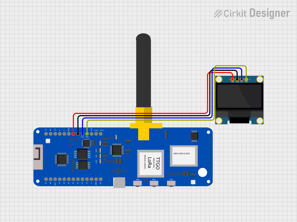
Usage Instructions
How to Use the Component in a Circuit
- Power Supply: Connect the VCC pin to a 3.3V or 5V power supply and the GND pin to the ground.
- I2C Communication: Connect the SCL pin to the I2C clock line (A5 on Arduino UNO) and the SDA pin to the I2C data line (A4 on Arduino UNO).
- Initialization: Use an appropriate library (e.g., Adafruit SSD1306) to initialize and control the display.
Important Considerations and Best Practices
- Power Supply: Ensure that the power supply voltage is within the specified range (3.3V - 5V) to avoid damaging the display.
- I2C Address: The default I2C address for the SSD1306 is 0x3C. Ensure that no other devices on the I2C bus share this address.
- Pull-up Resistors: If your microcontroller does not have internal pull-up resistors on the I2C lines, you may need to add external pull-up resistors (typically 4.7kΩ) to the SCL and SDA lines.
Example Code for Arduino UNO
#include <Wire.h>
#include <Adafruit_GFX.h>
#include <Adafruit_SSD1306.h>

// Define the screen dimensions
#define SCREEN_WIDTH 128
#define SCREEN_HEIGHT 64

// Create an instance of the display
Adafruit_SSD1306 display(SCREEN_WIDTH, SCREEN_HEIGHT, &Wire, -1);

void setup() {
  // Initialize the display
  if(!display.begin(SSD1306_I2C_ADDRESS, 0x3C)) {
    Serial.println(F("SSD1306 allocation failed"));
    for(;;);
  }
  display.display();
  delay(2000); // Pause for 2 seconds

  // Clear the buffer
  display.clearDisplay();

  // Display text
  display.setTextSize(1);      // Normal 1:1 pixel scale
  display.setTextColor(SSD1306_WHITE); // Draw white text
  display.setCursor(0,0);      // Start at top-left corner
  display.println(F("Hello, world!"));
  display.display();
}

void loop() {
  // Add your main code here, to run repeatedly
}
Troubleshooting and FAQs
Common Issues Users Might Face
Display Not Turning On:
- Solution: Check the power connections (VCC and GND). Ensure that the power supply voltage is within the specified range (3.3V - 5V).
No Display Output:
- Solution: Verify the I2C connections (SCL and SDA). Ensure that the I2C address (0x3C) is correctly set in the code. Check for any address conflicts on the I2C bus.
Flickering or Unstable Display:
- Solution: Ensure that the power supply is stable and capable of providing sufficient current. Check the I2C connections for loose or poor contacts.
Solutions and Tips for Troubleshooting
- Check Connections: Ensure that all connections are secure and correctly wired.
- Use Pull-up Resistors: If necessary, add pull-up resistors to the I2C lines.
- Library Compatibility: Ensure that you are using a compatible library (e.g., Adafruit SSD1306) and that it is correctly installed.
- Serial Monitor: Use the Serial Monitor to print debug messages and check for initialization errors.
By following this documentation, users should be able to effectively integrate and utilize the SSD1306 I2C OLED Display in their projects. Whether you are a beginner or an experienced user, this guide provides the necessary information to get started and troubleshoot common issues.