Cirkit Designer Logo
Cirkit Designer
Your all-in-one circuit design IDE
Home / 
Component Documentation

How to Use TTP224: Examples, Pinouts, and Specs

Image of TTP224
Cirkit Designer LogoDesign with TTP224 in Cirkit Designer

Introduction

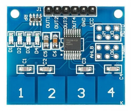
The TTP224 is a touch-sensitive switch IC manufactured by IOTWEBPLANET (Part ID: TTP224). This component is designed to detect touch inputs through capacitive sensing technology. It features a 4-channel input configuration, allowing up to four independent touch points to be registered. The TTP224 is widely used in applications such as touch panels, user interfaces, and other systems where mechanical switches are replaced with touch-sensitive controls. Its compact design and ease of integration make it a popular choice for modern electronic projects.

Explore Projects Built with TTP224

Use Cirkit Designer to design, explore, and prototype these projects online. Some projects support real-time simulation. Click "Open Project" to start designing instantly!
RTL8720DN-Based Interactive Button-Controlled TFT Display
Image of coba-coba: A project utilizing TTP224 in a practical application
This circuit features an RTL8720DN microcontroller interfaced with a China ST7735S 160x128 TFT LCD display and four pushbuttons. The microcontroller reads the states of the pushbuttons and displays their statuses on the TFT LCD, providing a visual feedback system for button presses.
Cirkit Designer LogoOpen Project in Cirkit Designer
ESP8266 NodeMCU Controlled Relay and Touch Sensor Interface with RGB LED Feedback
Image of NodeMcu: A project utilizing TTP224 in a practical application
This circuit features an ESP8266 NodeMCU microcontroller connected to a 4-channel relay module and four TTP233 touch sensors, as well as a WS2812 RGB LED strip. The NodeMCU's GPIO pins control the relay channels and receive input signals from the touch sensors, while one of its pins drives the data input of the LED strip. The circuit is designed to control power loads via the relays and provide user input through touch sensors, with visual feedback or status indication through the RGB LED strip.
Cirkit Designer LogoOpen Project in Cirkit Designer
Satellite-Based Timing and Navigation System with SDR and Atomic Clock Synchronization
Image of GPS 시스템 측정 구성도_Confirm: A project utilizing TTP224 in a practical application
This circuit appears to be a complex system involving power supply management, GPS and timing synchronization, and data communication. It includes a SI-TEX G1 Satellite Compass for GPS data, an XHTF1021 Atomic Rubidium Clock for precise timing, and Ettus USRP B200 units for software-defined radio communication. Power is supplied through various SMPS units and distributed via terminal blocks and DC jacks. Data communication is facilitated by Beelink MINI S12 N95 computers, RS232 splitters, and a 1000BASE-T Media Converter for network connectivity. RF Directional Couplers are used to interface antennas with the USRP units, and the entire system is likely contained within cases for protection and organization.
Cirkit Designer LogoOpen Project in Cirkit Designer
Temperature-Controlled Heating System with SSR and Titanium Resistor
Image of Wire Cut Four Slider 33-2 & 33-3 (Old): A project utilizing TTP224 in a practical application
This circuit is a temperature control system that uses a temperature controller to regulate a heating titanium resistor via a solid-state relay (SSR). The power transformer supplies the necessary voltage to the temperature controller, which in turn controls the SSR to manage the heating element.
Cirkit Designer LogoOpen Project in Cirkit Designer

Explore Projects Built with TTP224

Use Cirkit Designer to design, explore, and prototype these projects online. Some projects support real-time simulation. Click "Open Project" to start designing instantly!
Image of coba-coba: A project utilizing TTP224 in a practical application
RTL8720DN-Based Interactive Button-Controlled TFT Display
This circuit features an RTL8720DN microcontroller interfaced with a China ST7735S 160x128 TFT LCD display and four pushbuttons. The microcontroller reads the states of the pushbuttons and displays their statuses on the TFT LCD, providing a visual feedback system for button presses.
Cirkit Designer LogoOpen Project in Cirkit Designer
Image of NodeMcu: A project utilizing TTP224 in a practical application
ESP8266 NodeMCU Controlled Relay and Touch Sensor Interface with RGB LED Feedback
This circuit features an ESP8266 NodeMCU microcontroller connected to a 4-channel relay module and four TTP233 touch sensors, as well as a WS2812 RGB LED strip. The NodeMCU's GPIO pins control the relay channels and receive input signals from the touch sensors, while one of its pins drives the data input of the LED strip. The circuit is designed to control power loads via the relays and provide user input through touch sensors, with visual feedback or status indication through the RGB LED strip.
Cirkit Designer LogoOpen Project in Cirkit Designer
Image of GPS 시스템 측정 구성도_Confirm: A project utilizing TTP224 in a practical application
Satellite-Based Timing and Navigation System with SDR and Atomic Clock Synchronization
This circuit appears to be a complex system involving power supply management, GPS and timing synchronization, and data communication. It includes a SI-TEX G1 Satellite Compass for GPS data, an XHTF1021 Atomic Rubidium Clock for precise timing, and Ettus USRP B200 units for software-defined radio communication. Power is supplied through various SMPS units and distributed via terminal blocks and DC jacks. Data communication is facilitated by Beelink MINI S12 N95 computers, RS232 splitters, and a 1000BASE-T Media Converter for network connectivity. RF Directional Couplers are used to interface antennas with the USRP units, and the entire system is likely contained within cases for protection and organization.
Cirkit Designer LogoOpen Project in Cirkit Designer
Image of Wire Cut Four Slider 33-2 & 33-3 (Old): A project utilizing TTP224 in a practical application
Temperature-Controlled Heating System with SSR and Titanium Resistor
This circuit is a temperature control system that uses a temperature controller to regulate a heating titanium resistor via a solid-state relay (SSR). The power transformer supplies the necessary voltage to the temperature controller, which in turn controls the SSR to manage the heating element.
Cirkit Designer LogoOpen Project in Cirkit Designer

Common Applications

  • Touch-sensitive control panels
  • Home automation systems
  • Consumer electronics (e.g., appliances, remote controls)
  • Interactive kiosks and displays
  • Replacement for mechanical buttons in embedded systems

Technical Specifications

The TTP224 is a versatile and efficient touch-sensing IC. Below are its key technical details:

Parameter Value
Operating Voltage 2.4V to 5.5V
Operating Current 2.5mA (typical)
Number of Channels 4
Response Time ~100ms
Output Type Active low or active high (configurable)
Interface Digital
Operating Temperature -40°C to +85°C
Package Type SOP-16

Pin Configuration and Descriptions

The TTP224 IC has 16 pins, with the following configuration:

Pin Number Pin Name Description
1 VDD Power supply (2.4V to 5.5V)
2 OUT1 Output for touch key 1
3 OUT2 Output for touch key 2
4 OUT3 Output for touch key 3
5 OUT4 Output for touch key 4
6 AHLB Output mode selection (active high/low)
7 MODE Operating mode selection
8 GND Ground
9-12 TP1-TP4 Touch input channels 1 to 4
13 VSS Ground (internally connected to GND)
14 SLRFTM Response time adjustment
15 NC No connection
16 NC No connection

Usage Instructions

The TTP224 is straightforward to use in a circuit. Below are the steps and considerations for integrating it into your project:

Basic Circuit Connection

  1. Power Supply: Connect the VDD pin to a 2.4V–5.5V power source and the GND pin to ground.
  2. Touch Inputs: Attach touch-sensitive electrodes (e.g., copper pads) to the TP1–TP4 pins. Ensure the electrodes are properly isolated from other conductive materials.
  3. Outputs: Connect the OUT1–OUT4 pins to the desired control circuit (e.g., microcontroller inputs or LEDs).
  4. Mode Selection: Use the MODE pin to configure the operating mode:
    • Leave the MODE pin floating for low-power mode.
    • Connect the MODE pin to GND for fast mode.
  5. Output Configuration: Use the AHLB pin to set the output type:
    • Connect to VDD for active high output.
    • Connect to GND for active low output.

Example: Connecting to an Arduino UNO

The TTP224 can be easily interfaced with an Arduino UNO to detect touch inputs. Below is an example circuit and code:

Circuit Diagram

  • Connect the TTP224's VDD to the Arduino's 5V pin.
  • Connect the TTP224's GND to the Arduino's GND.
  • Connect OUT1–OUT4 to Arduino digital pins 2–5, respectively.
  • Attach touch electrodes to TP1–TP4.

Arduino Code

// TTP224 Touch Sensor Example with Arduino UNO
// This code reads touch inputs from the TTP224 and prints the status to the Serial Monitor.

#define TOUCH1 2  // OUT1 connected to digital pin 2
#define TOUCH2 3  // OUT2 connected to digital pin 3
#define TOUCH3 4  // OUT3 connected to digital pin 4
#define TOUCH4 5  // OUT4 connected to digital pin 5

void setup() {
  // Initialize serial communication
  Serial.begin(9600);

  // Set touch sensor pins as inputs
  pinMode(TOUCH1, INPUT);
  pinMode(TOUCH2, INPUT);
  pinMode(TOUCH3, INPUT);
  pinMode(TOUCH4, INPUT);
}

void loop() {
  // Read the state of each touch input
  bool touch1 = digitalRead(TOUCH1);
  bool touch2 = digitalRead(TOUCH2);
  bool touch3 = digitalRead(TOUCH3);
  bool touch4 = digitalRead(TOUCH4);

  // Print the touch status to the Serial Monitor
  Serial.print("Touch 1: "); Serial.print(touch1);
  Serial.print(" | Touch 2: "); Serial.print(touch2);
  Serial.print(" | Touch 3: "); Serial.print(touch3);
  Serial.print(" | Touch 4: "); Serial.println(touch4);

  delay(100);  // Small delay for stability
}

Best Practices

  • Use proper decoupling capacitors (e.g., 0.1µF) near the VDD pin to stabilize the power supply.
  • Ensure the touch electrodes are clean and free from contaminants for optimal sensitivity.
  • Avoid placing the TTP224 near high-frequency noise sources to prevent interference.

Troubleshooting and FAQs

Common Issues

  1. Touch Inputs Not Detected

    • Cause: Poor connection to the touch electrodes or insufficient power supply.
    • Solution: Check the connections and ensure the power supply voltage is within the specified range.
  2. False Triggers

    • Cause: Electrical noise or improper grounding.
    • Solution: Add a pull-down resistor to the output pins or improve the grounding.
  3. Slow Response

    • Cause: Incorrect mode configuration.
    • Solution: Set the MODE pin to GND for fast mode.

FAQs

  1. Can the TTP224 detect multiple touches simultaneously?

    • Yes, the TTP224 can detect up to four independent touch inputs simultaneously.
  2. What materials can be used for touch electrodes?

    • Common materials include copper tape, conductive ink, or PCB traces.
  3. Is the TTP224 compatible with 3.3V systems?

    • Yes, the TTP224 operates within a voltage range of 2.4V to 5.5V, making it compatible with 3.3V systems.
  4. How can I increase touch sensitivity?

    • Increase the size of the touch electrodes or reduce the thickness of any insulating material covering them.

By following this documentation, you can effectively integrate the TTP224 into your projects and troubleshoot any issues that arise.