How to Use uCup_BasePCB_Reuse: Examples, Pinouts, and Specs
Introduction
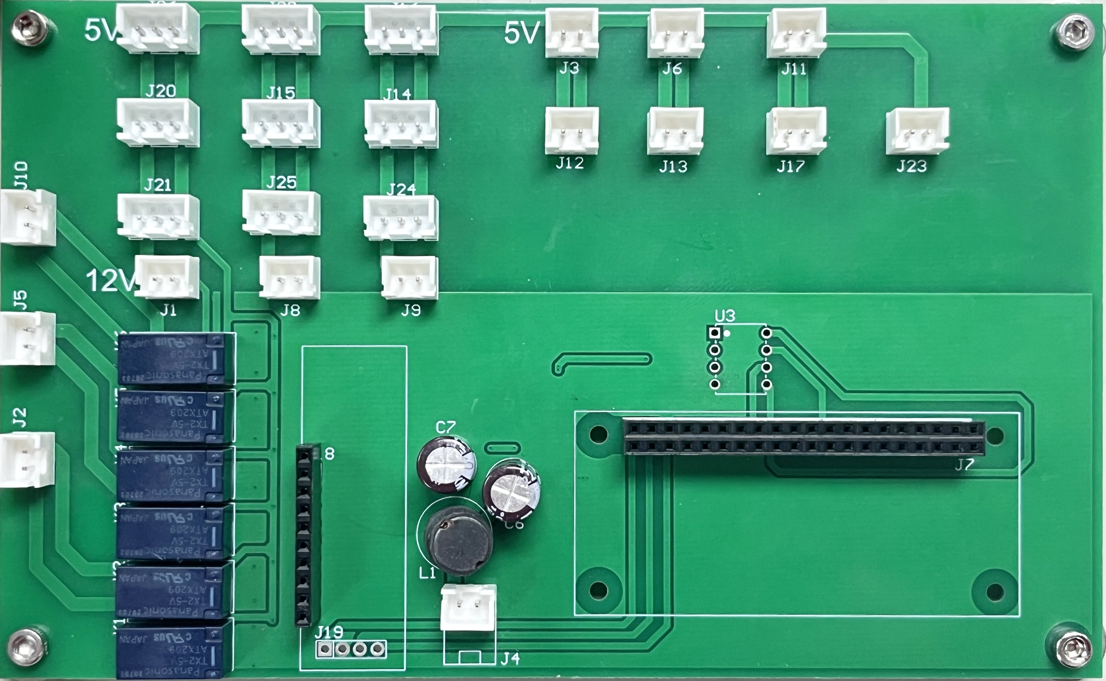
The uCup_BasePCB_Reuse is a reusable base printed circuit board (PCB) designed by uCup with the part ID ESP32_A7670G. This PCB is tailored for the uCup project, providing a versatile platform for integrating and modifying electronic components. It is ideal for prototyping, modular designs, and applications requiring flexibility and reusability. The board is compatible with a wide range of microcontrollers, sensors, and communication modules, making it suitable for IoT, robotics, and custom electronics projects.
Explore Projects Built with uCup_BasePCB_Reuse

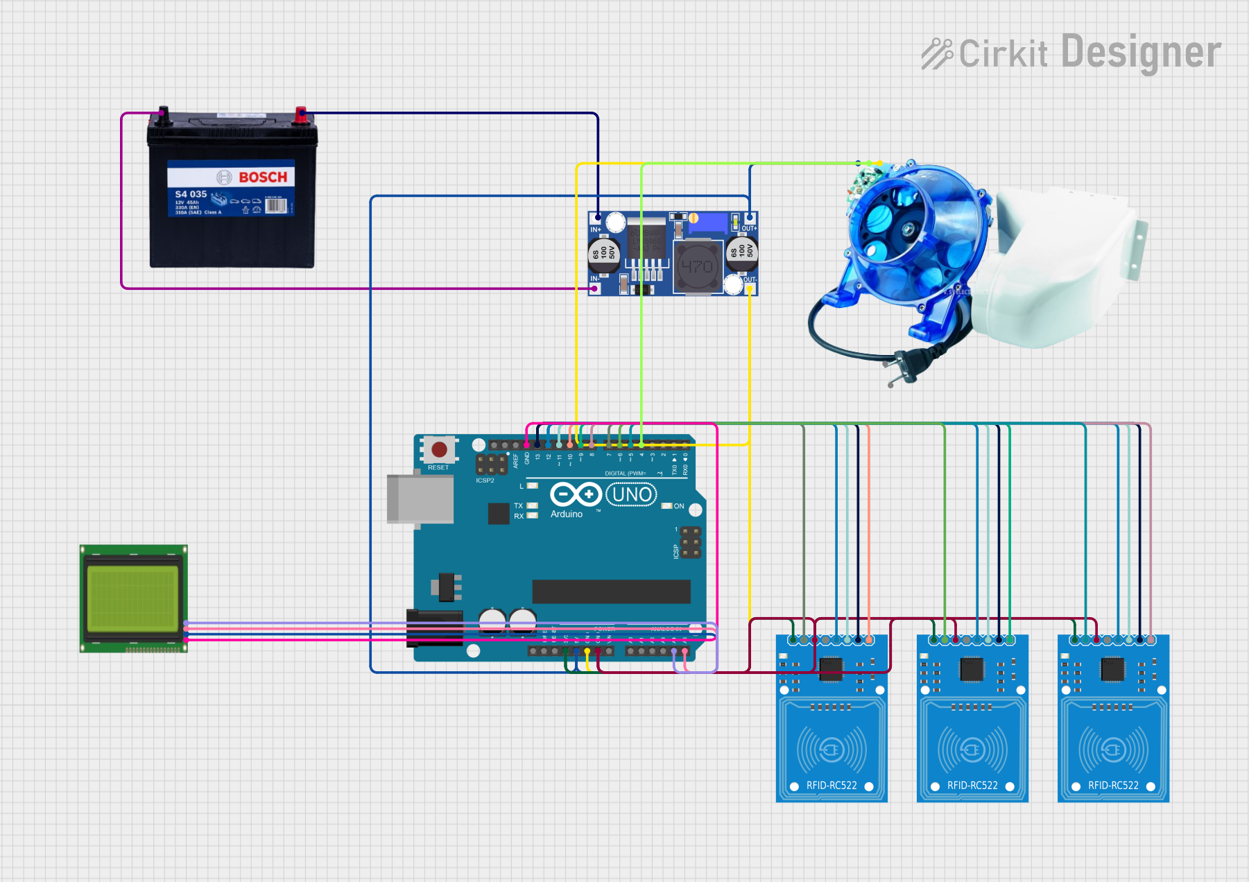
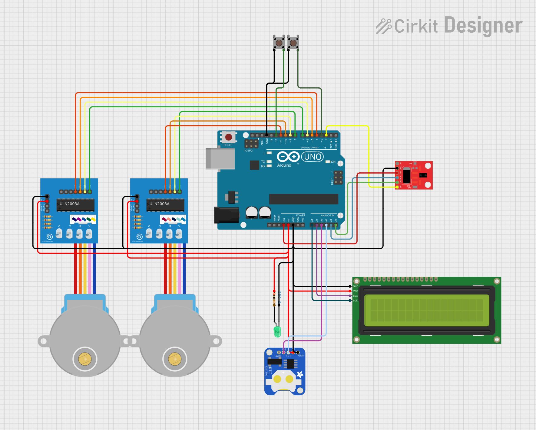

Explore Projects Built with uCup_BasePCB_Reuse
Common Applications and Use Cases
- IoT Prototyping: Easily integrate sensors, actuators, and communication modules.
- Robotics: Use as a control board for small to medium-sized robots.
- Educational Projects: Ideal for teaching circuit design and prototyping.
- Custom Electronics: Build and test custom circuits with reusable components.
- Smart Devices: Develop smart home or wearable technology solutions.
Technical Specifications
Key Technical Details
| Parameter | Specification |
|---|---|
| Manufacturer | uCup |
| Part ID | ESP32_A7670G |
| PCB Dimensions | 100mm x 80mm x 1.6mm |
| Supported Voltage Range | 3.3V to 5V |
| Maximum Current Capacity | 2A |
| Communication Interfaces | UART, I2C, SPI, GPIO |
| Microcontroller Support | ESP32, ESP8266, Arduino, Raspberry Pi, and others |
| Mounting Options | Screw holes and solder pads |
| Operating Temperature | -40°C to 85°C |
| PCB Material | FR4 (Flame Retardant 4) |
| Surface Finish | HASL (Hot Air Solder Leveling) |
Pin Configuration and Descriptions
The uCup_BasePCB_Reuse features a modular pin layout for easy integration. Below is the pin configuration:
| Pin Name | Type | Description |
|---|---|---|
| VIN | Power Input | Main power input (3.3V to 5V). |
| GND | Ground | Common ground for the circuit. |
| GPIO1-GPIO16 | Digital I/O | General-purpose input/output pins. |
| SDA | I2C Data | Data line for I2C communication. |
| SCL | I2C Clock | Clock line for I2C communication. |
| TX | UART Transmit | Transmit pin for UART communication. |
| RX | UART Receive | Receive pin for UART communication. |
| MOSI | SPI Data Out | Master Out Slave In for SPI communication. |
| MISO | SPI Data In | Master In Slave Out for SPI communication. |
| SCK | SPI Clock | Clock line for SPI communication. |
| 3V3 | Power Output | 3.3V regulated output for peripherals. |
| 5V | Power Output | 5V regulated output for peripherals. |
Usage Instructions
How to Use the Component in a Circuit
- Powering the PCB: Connect a 3.3V or 5V power source to the VIN pin and GND pin.
- Connecting a Microcontroller:
- Mount an ESP32, Arduino, or other compatible microcontroller onto the PCB.
- Use the GPIO, I2C, SPI, or UART pins to interface with external components.
- Adding Peripherals:
- Solder sensors, actuators, or communication modules to the appropriate pins.
- Ensure proper voltage levels for connected peripherals.
- Programming:
- Use a USB-to-serial adapter or onboard programming interface to upload code to the microcontroller.
- Testing:
- Power the circuit and verify functionality using a multimeter or oscilloscope.
Important Considerations and Best Practices
- Voltage Compatibility: Ensure all connected components operate within the 3.3V to 5V range.
- Current Limits: Do not exceed the 2A maximum current capacity of the PCB.
- Soldering: Use a fine-tipped soldering iron and avoid overheating the PCB pads.
- Static Protection: Handle the PCB with care to prevent electrostatic discharge (ESD) damage.
- Mounting: Use the provided screw holes to securely mount the PCB in your project enclosure.
Example: Connecting to an Arduino UNO
Below is an example of how to connect the uCup_BasePCB_Reuse to an Arduino UNO and control an LED:
Circuit Connections
- Connect the Arduino's 5V pin to the VIN pin on the PCB.
- Connect the Arduino's GND pin to the GND pin on the PCB.
- Connect a digital pin (e.g., D9) on the Arduino to GPIO1 on the PCB.
- Connect an LED to GPIO1 with a 220-ohm resistor in series.
Arduino Code
// Example code to blink an LED connected to GPIO1 on the uCup_BasePCB_Reuse

#define LED_PIN 9  // GPIO1 on the PCB is connected to Arduino pin D9

void setup() {
  pinMode(LED_PIN, OUTPUT);  // Set the LED pin as an output
}

void loop() {
  digitalWrite(LED_PIN, HIGH);  // Turn the LED on
  delay(1000);                  // Wait for 1 second
  digitalWrite(LED_PIN, LOW);   // Turn the LED off
  delay(1000);                  // Wait for 1 second
}
Troubleshooting and FAQs
Common Issues and Solutions
PCB Not Powering On
- Cause: Incorrect power supply voltage.
- Solution: Ensure the input voltage is between 3.3V and 5V.
Microcontroller Not Responding
- Cause: Incorrect pin connections or faulty programming.
- Solution: Double-check connections and re-upload the code.
Peripheral Devices Not Working
- Cause: Voltage mismatch or incorrect wiring.
- Solution: Verify the voltage requirements and wiring of the peripherals.
Overheating
- Cause: Excessive current draw.
- Solution: Ensure the total current does not exceed 2A.
FAQs
Q: Can I use this PCB with a Raspberry Pi?
- A: Yes, the PCB is compatible with Raspberry Pi GPIO pins.
Q: Is the PCB suitable for outdoor use?
- A: The PCB is not weatherproof. Use a protective enclosure for outdoor applications.
Q: Can I power the PCB with a battery?
- A: Yes, as long as the battery provides a stable voltage between 3.3V and 5V.
Q: What is the maximum number of peripherals I can connect?
- A: This depends on the power and GPIO pin availability. Ensure the total current draw does not exceed 2A.
This concludes the documentation for the uCup_BasePCB_Reuse. For further assistance, refer to the manufacturer's datasheet or contact uCup support.