How to Use 741 ic: Examples, Pinouts, and Specs
Introduction
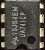
The 741 IC, manufactured by Dixon Technologies (India) Ltd. (Part ID: 741 op-amp), is a general-purpose operational amplifier (op-amp) widely used in analog electronics. It is designed for a variety of applications, including signal amplification, active filtering, and mathematical operations such as addition, subtraction, integration, and differentiation. The 741 IC is known for its high gain, low output impedance, and ease of use, making it a staple in both educational and professional circuits.
Explore Projects Built with 741 ic

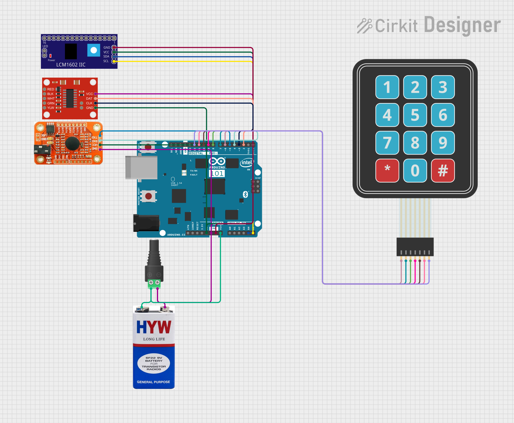
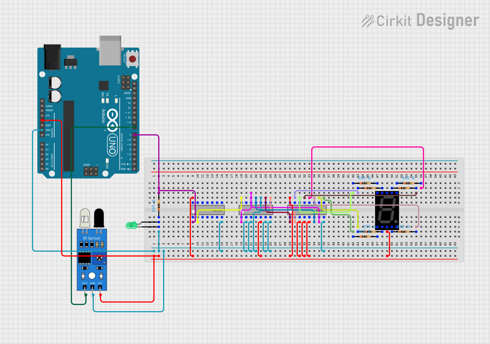
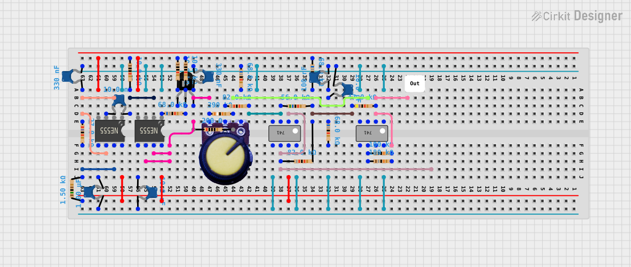
Explore Projects Built with 741 ic
Common Applications
- Signal amplification in audio and instrumentation systems
- Active filters (low-pass, high-pass, band-pass, and band-stop)
- Analog computation (addition, subtraction, integration, differentiation)
- Voltage comparators
- Oscillators and waveform generators
Technical Specifications
Below are the key technical details of the 741 IC:
| Parameter | Value |
|---|---|
| Supply Voltage (Vcc) | ±5V to ±18V |
| Input Offset Voltage | 2 mV (typical) |
| Input Bias Current | 80 nA (typical) |
| Input Impedance | 2 MΩ |
| Output Impedance | 75 Ω |
| Voltage Gain | 200,000 (open-loop, typical) |
| Slew Rate | 0.5 V/μs |
| Bandwidth (Unity Gain) | 1 MHz |
| Operating Temperature Range | 0°C to 70°C |
| Package Type | DIP-8, SOIC-8 |
Pin Configuration and Descriptions
The 741 IC is an 8-pin device. Below is the pinout and description:
| Pin Number | Pin Name | Description |
|---|---|---|
| 1 | Offset Null | Used for offset voltage adjustment (connect to a potentiometer if needed). |
| 2 | Inverting Input | The inverting input terminal (-) of the op-amp. |
| 3 | Non-Inverting Input | The non-inverting input terminal (+) of the op-amp. |
| 4 | V- (Negative Supply) | Connect to the negative power supply (e.g., -Vcc). |
| 5 | Offset Null | Used for offset voltage adjustment (connect to a potentiometer if needed). |
| 6 | Output | The output terminal of the op-amp. |
| 7 | V+ (Positive Supply) | Connect to the positive power supply (e.g., +Vcc). |
| 8 | NC (No Connection) | Not connected internally; leave unconnected. |
Usage Instructions
How to Use the 741 IC in a Circuit
- Power Supply: Connect the positive supply voltage (Vcc) to Pin 7 and the negative supply voltage (Vee) to Pin 4. The supply voltage should be within the range of ±5V to ±18V.
- Input Connections:
- Connect the signal to be amplified to either the inverting input (Pin 2) or the non-inverting input (Pin 3), depending on the desired configuration (inverting or non-inverting).
- Use appropriate resistors to set the gain of the amplifier.
- Output Connection: The amplified signal will be available at Pin 6. Connect this pin to the load or the next stage of the circuit.
- Offset Null Adjustment: If offset voltage correction is required, connect a 10 kΩ potentiometer between Pins 1 and 5, with the wiper connected to the negative supply (Pin 4).
Important Considerations and Best Practices
- Bypass Capacitors: Place decoupling capacitors (e.g., 0.1 μF) close to the power supply pins to reduce noise and improve stability.
- Input Impedance: Ensure the source impedance is low enough to avoid signal attenuation.
- Avoid Saturation: Ensure the input signal and gain are within limits to prevent the output from saturating.
- Thermal Considerations: Operate the IC within the specified temperature range (0°C to 70°C) to avoid performance degradation.
Example: Using the 741 IC with an Arduino UNO
The 741 IC can be used to amplify an analog signal before feeding it into the Arduino's analog input. Below is an example of a non-inverting amplifier circuit with a gain of 11.
Circuit Diagram
- Connect:
- Pin 7 to +12V and Pin 4 to -12V.
- The input signal to Pin 3 (non-inverting input).
- A resistor (R1 = 1 kΩ) between Pin 2 (inverting input) and ground.
- A resistor (R2 = 10 kΩ) between Pin 2 and Pin 6 (output).
- Pin 6 to the Arduino's analog input (e.g., A0).
Arduino Code
// Arduino code to read the amplified signal from the 741 IC
const int analogPin = A0; // Analog pin connected to the 741 IC output
int sensorValue = 0;      // Variable to store the analog reading

void setup() {
  Serial.begin(9600); // Initialize serial communication at 9600 baud
}

void loop() {
  sensorValue = analogRead(analogPin); // Read the analog value
  float voltage = sensorValue * (5.0 / 1023.0); // Convert to voltage
  Serial.print("Amplified Voltage: ");
  Serial.println(voltage); // Print the voltage to the Serial Monitor
  delay(500); // Wait for 500 ms before the next reading
}
Troubleshooting and FAQs
Common Issues and Solutions
No Output Signal:
- Check the power supply connections (Pins 4 and 7).
- Verify that the input signal is within the acceptable range.
- Ensure the gain-setting resistors are correctly connected.
Distorted Output:
- Reduce the input signal amplitude to avoid saturation.
- Check for proper decoupling capacitors near the power supply pins.
High Offset Voltage:
- Use a potentiometer between Pins 1 and 5 to nullify the offset voltage.
Oscillations or Noise:
- Add bypass capacitors (e.g., 0.1 μF) close to the power supply pins.
- Ensure proper grounding and minimize long signal paths.
FAQs
Q1: Can the 741 IC be used for high-frequency applications?
A1: The 741 IC has a limited bandwidth of 1 MHz, making it unsuitable for high-frequency applications. Consider using a high-speed op-amp for such cases.
Q2: What is the maximum output current of the 741 IC?
A2: The 741 IC can typically source or sink up to 20 mA. Exceeding this limit may damage the IC.
Q3: Can the 741 IC operate with a single power supply?
A3: Yes, the 741 IC can operate with a single supply, but the input signal and output range must be biased appropriately to stay within the operating range.
Q4: How do I calculate the gain of a 741 amplifier?
A4: For a non-inverting amplifier, the gain is given by ( 1 + \frac{R2}{R1} ), where ( R1 ) is the resistor between the inverting input and ground, and ( R2 ) is the resistor between the inverting input and the output.