How to Use Adafruit Hallowing M4: Examples, Pinouts, and Specs
Introduction
The Adafruit Hallowing M4 is a versatile and powerful development board designed for creating interactive projects and games. Based on the ATSAMD51 microcontroller, it is equipped with a full-color TFT display, user interface buttons, various sensors, and LEDs. This board is particularly popular among hobbyists and educators for Halloween-themed projects, wearable electronics, and prototyping.
Explore Projects Built with Adafruit Hallowing M4
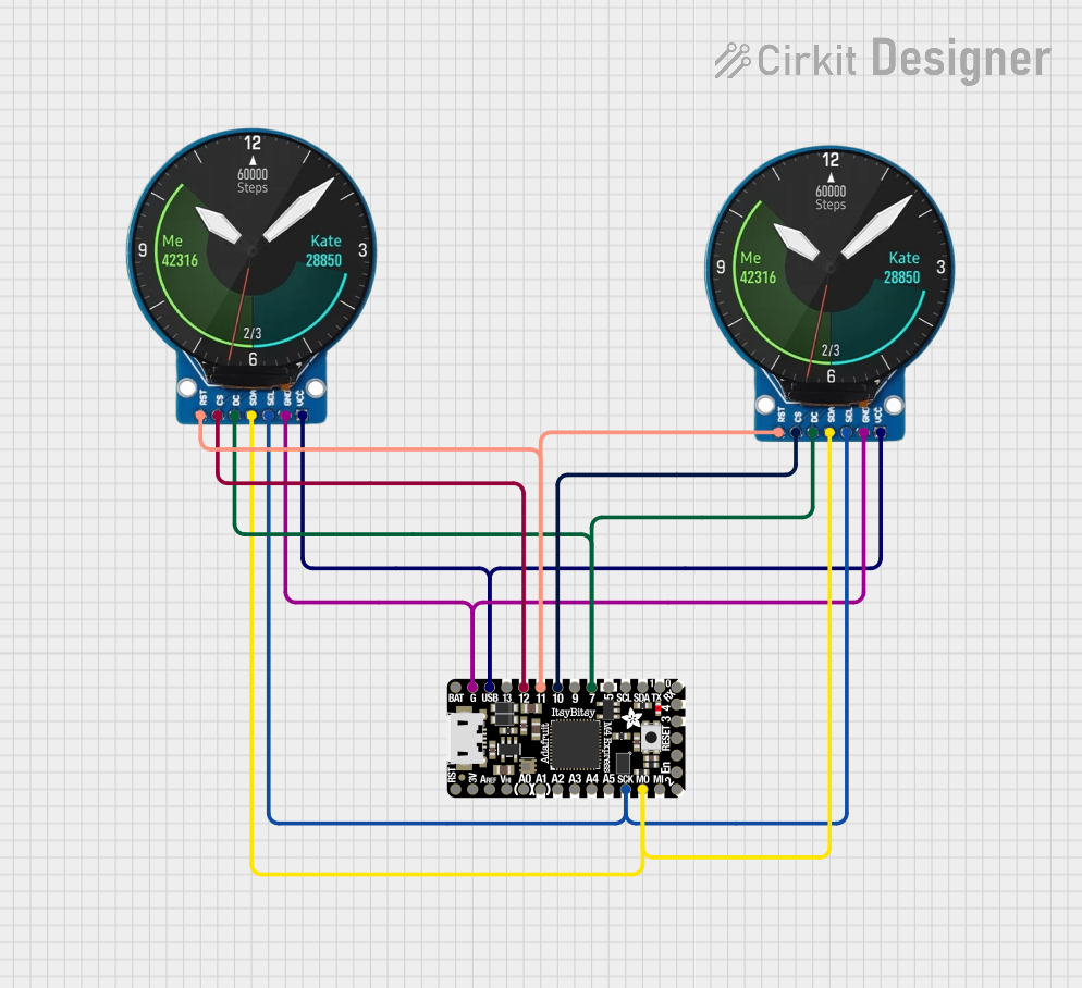
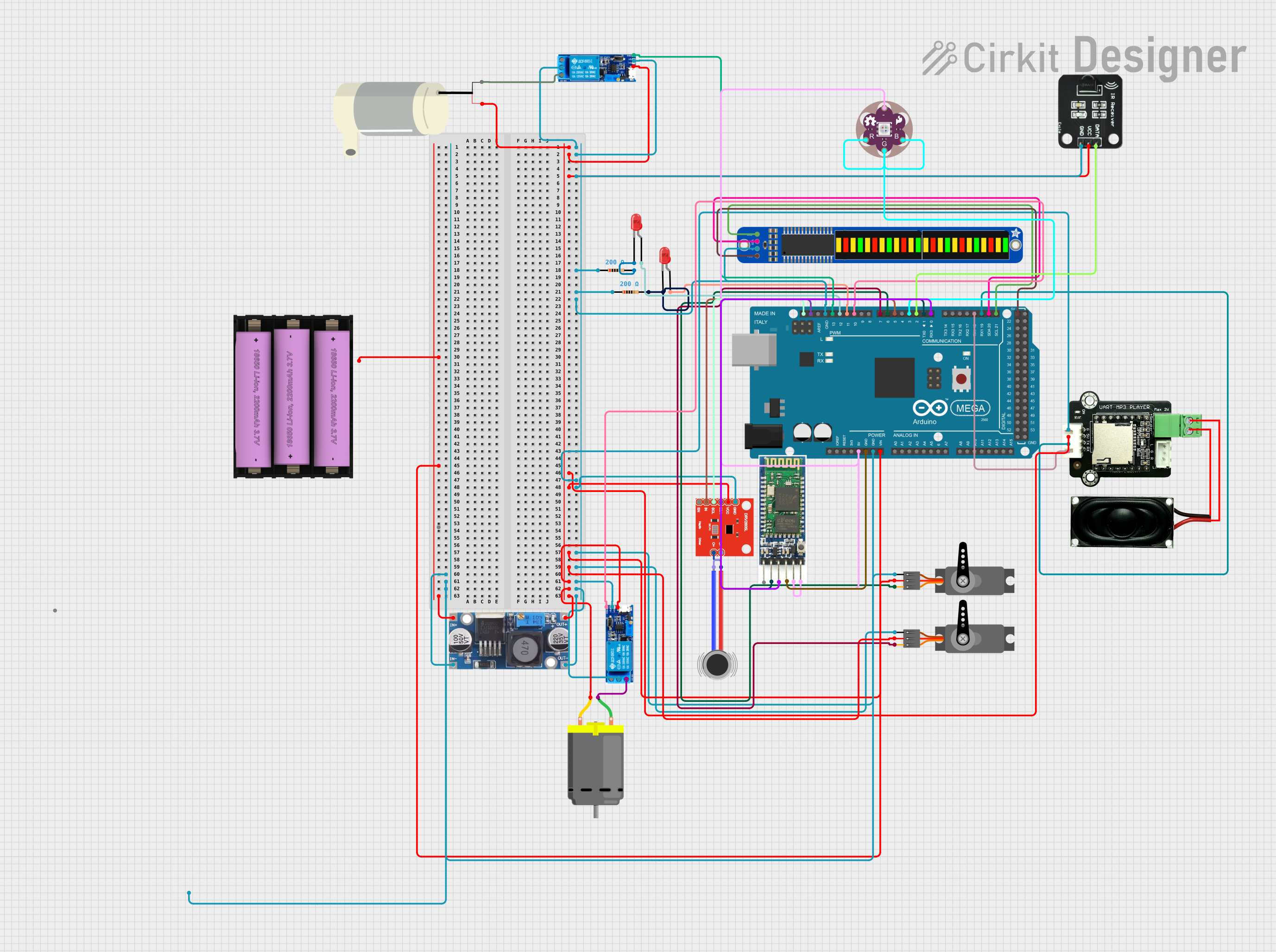


Explore Projects Built with Adafruit Hallowing M4
Common Applications and Use Cases
- Interactive costumes and props
- Educational tools for teaching programming and electronics
- Portable game consoles
- DIY electronic gadgets
- Prototyping IoT devices
Technical Specifications
Key Technical Details
- Microcontroller: ATSAMD51 32-bit Cortex M4 core running at 120 MHz
- Flash Memory: 512 KB
- RAM: 192 KB
- Display: 1.44" 128x128 full-color TFT
- Sensors: 9-DOF (accelerometer, magnetometer, gyroscope)
- Sound: Built-in buzzer/speaker
- Battery: 3.7V Lithium Polymer battery connector
- Connectivity: JST connectors for NeoPixel and sensor input
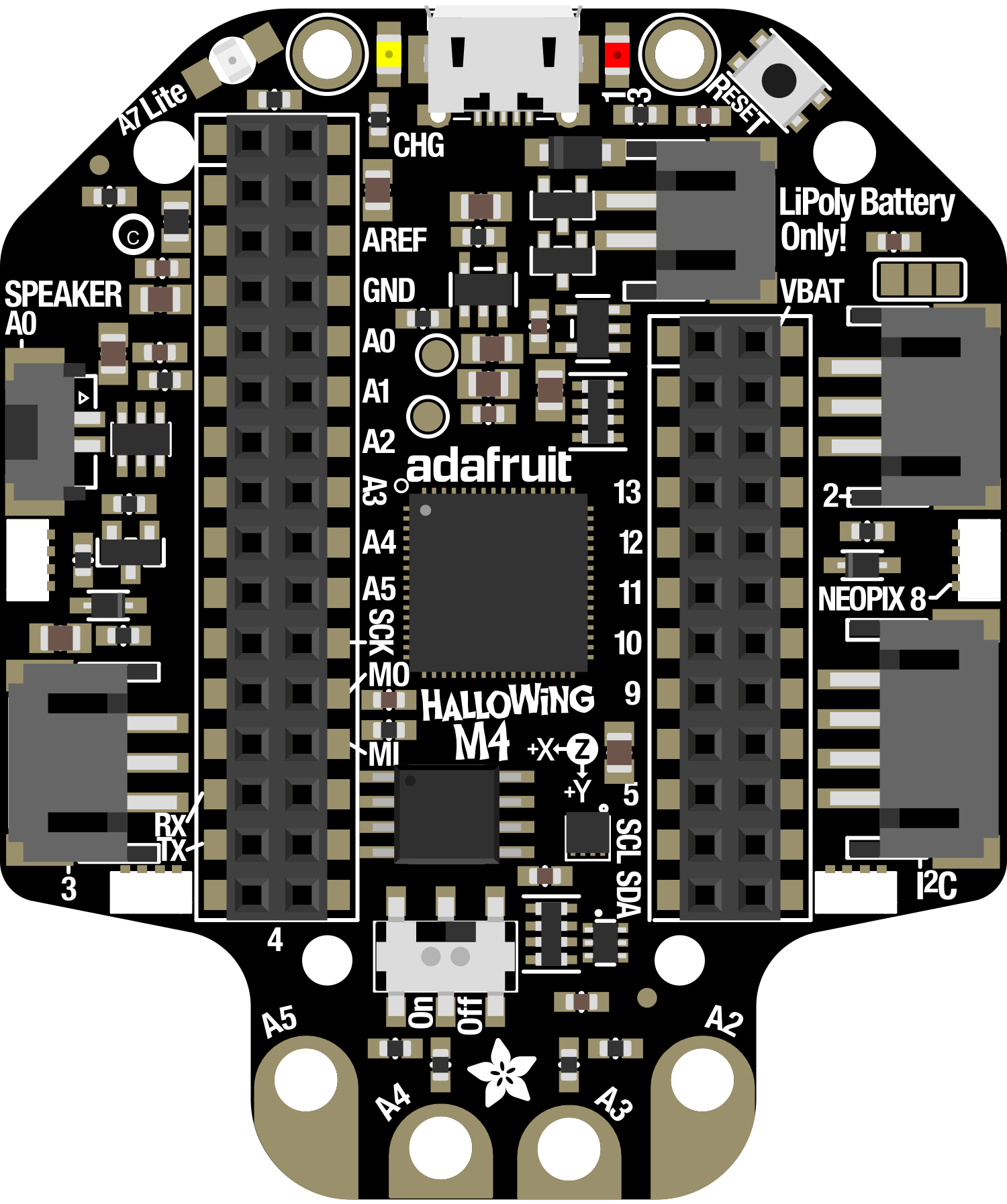
Pin Configuration and Descriptions
| Pin Number | Function | Description |
|---|---|---|
| 1 | VBAT | Battery input for an optional LiPoly battery |
| 2 | EN | Enable pin, can be used to turn off the power |
| 3 | GND | Ground |
| 4 | USB | USB connection for programming and power |
| 5 | SDA | I2C data line |
| 6 | SCL | I2C clock line |
| 7 | #0 - #13 | General purpose I/O pins |
| 8 | A0 - A5 | Analog input pins |
| 9 | TX | UART transmit |
| 10 | RX | UART receive |
| 11 | SCK/MOSI/MISO | SPI pins |
| 12 | RST | Reset pin |
| 13 | 3.3V | 3.3V power output |
Usage Instructions
How to Use the Component in a Circuit
- Powering the Board: Connect a 3.7V Lithium Polymer battery to the VBAT pin for portable applications, or power the board via the USB connection.
- Programming: Use the USB connection to program the Hallowing M4 with the Arduino IDE or CircuitPython.
- Display: Utilize the built-in TFT display to show graphics, text, and animations.
- Sensors: Access the onboard 9-DOF sensors for motion tracking and orientation.
- Expansion: Connect additional sensors, NeoPixels, or other peripherals using the I/O pins.
Important Considerations and Best Practices
- Always ensure the power supply is within the specified range to prevent damage.
- When handling the board, be cautious of electrostatic discharge by grounding yourself.
- Avoid placing the board on conductive surfaces to prevent short circuits.
- Use proper decoupling capacitors when connecting external components to reduce noise.
Troubleshooting and FAQs
Common Issues Users Might Face
- Display Not Working: Ensure the display ribbon cable is properly seated and the board is powered correctly.
- Unresponsive Board: Check the USB cable and connection. Try pressing the reset button.
- Sensor Inaccuracy: Calibrate the sensors if readings seem off.
Solutions and Tips for Troubleshooting
- Verify all connections and solder joints are secure and correct.
- Update to the latest firmware and libraries.
- Consult the Adafruit forums and guides for additional support.
FAQs
Q: Can I power the Hallowing M4 with a different battery? A: Yes, as long as it's 3.7V and can connect to the JST-PH battery connector.
Q: How do I upload code to the Hallowing M4? A: Connect the board to your computer via USB and use the Arduino IDE or CircuitPython editor to upload your code.
Q: What programming languages can I use with the Hallowing M4? A: The board supports programming with Arduino (C/C++) and CircuitPython (Python).
Example Code for Arduino UNO
Below is a simple example code that demonstrates how to use the Hallowing M4 with an Arduino UNO. This code will initialize the display and show a message.
#include <Adafruit_GFX.h>    // Core graphics library
#include <Adafruit_ST7735.h> // Hardware-specific library for ST7735
#include <SPI.h>

// Pin definitions for the Hallowing M4
#define TFT_CS     6
#define TFT_RST    7
#define TFT_DC     8

// Initialize the ST7735 TFT display
Adafruit_ST7735 tft = Adafruit_ST7735(TFT_CS, TFT_DC, TFT_RST);

void setup() {
  tft.initR(INITR_144GREENTAB); // Initialize display with the correct settings
  tft.fillScreen(ST7735_BLACK);  // Clear the screen to black
  tft.setCursor(0, 0);           // Set the cursor to the top-left corner
  tft.setTextColor(ST7735_WHITE); // Set the text color to white
  tft.setTextWrap(true);          // Allow text to wrap to the next line
  tft.print("Hello, Hallowing M4!"); // Print a message to the display
}

void loop() {
  // No need to do anything here for this simple example
}
Remember to install the necessary libraries through the Arduino Library Manager before uploading the code to the Hallowing M4. This example assumes you have basic knowledge of using the Arduino IDE and connecting the Hallowing M4 to an Arduino UNO.