How to Use AMS1117: Examples, Pinouts, and Specs
Introduction
The AMS1117 is a series of low dropout voltage regulators that can deliver up to 1A of output current. These regulators are designed to provide a stable output voltage with a small dropout voltage, making them ideal for battery-powered devices where extending battery life is a key concern. The AMS1117 series is commonly used in a variety of applications, including microcontroller power supplies, battery chargers, and linear power supplies.
Explore Projects Built with AMS1117


Explore Projects Built with AMS1117
Common Applications and Use Cases
- Power supply for microcontrollers and digital systems
- Post-regulation for switching power supplies
- Battery-powered devices
- Peripheral power supplies
Technical Specifications
Key Technical Details
- Output Current: Up to 1A
- Dropout Voltage: Typically 1.1V at 800mA of load
- Output Voltage Options: 1.2V, 1.5V, 1.8V, 2.5V, 3.3V, 5.0V, and adjustable versions
- Maximum Input Voltage: 15V
- Quiescent Current: 5mA (typical)
- Line Regulation: 0.2% max
- Load Regulation: 0.4% max
- Operating Temperature Range: -40°C to +125°C
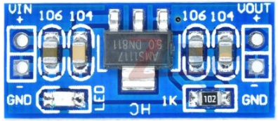
Pin Configuration and Descriptions
| Pin Number | Name | Description |
|---|---|---|
| 1 | ADJ/GND | Ground (for fixed voltage versions) or adjustment pin (for adjustable version) |
| 2 | VOUT | Regulated output voltage |
| 3 | VIN | Input voltage |
Usage Instructions
How to Use the AMS1117 in a Circuit
- Connect the input voltage (which should be higher than the desired output voltage plus the dropout voltage) to the VIN pin.
- Connect the VOUT pin to the load that requires the regulated voltage.
- For fixed voltage versions, connect the ADJ/GND pin to the ground. For adjustable versions, connect a resistor divider network to set the output voltage as per the datasheet recommendations.
- Place a tantalum or ceramic capacitor (typically 10µF) on the input and output pins to improve stability. Refer to the datasheet for specific capacitor recommendations.
Important Considerations and Best Practices
- Ensure that the input voltage does not exceed the maximum rating of 15V.
- The dropout voltage is the minimum difference between the input and output voltages at which the regulator can maintain the output voltage. Always account for this when designing your circuit.
- Heat dissipation is important. The AMS1117 can dissipate heat through its tab, so it may require a heatsink if the output current is high or if the input-output voltage differential is large.
- The output capacitor is critical for stability. Low ESR capacitors are recommended for better performance.
Troubleshooting and FAQs
Common Issues Users Might Face
- Output Voltage Fluctuation: This can be due to insufficient input voltage, excessive load, or inadequate capacitors. Ensure that the input voltage is sufficient and that the capacitors are of the recommended value and type.
- Overheating: If the AMS1117 is overheating, it may be due to excessive current draw or a high input-output voltage differential. Consider using a heatsink or reducing the load.
Solutions and Tips for Troubleshooting
- Always check the input voltage first to ensure it is within the specified range.
- Verify that the capacitors are correctly placed and are of the type and value specified in the datasheet.
- If the regulator is overheating, reduce the load or improve heat dissipation with a heatsink.
FAQs
Q: Can I use the AMS1117 without a heatsink? A: It depends on the load current and the voltage differential. For low current applications or when the input-output differential is small, a heatsink may not be necessary. However, for higher currents or larger differentials, a heatsink is recommended.
Q: What is the maximum input voltage for the AMS1117? A: The maximum input voltage is 15V. Exceeding this voltage can damage the regulator.
Q: How do I choose the output capacitors? A: The datasheet typically recommends a 10µF tantalum or ceramic capacitor on the input and output for stability. The exact value may vary based on the application.
Q: Can the AMS1117 be used to step up voltage? A: No, the AMS1117 is a linear regulator designed to step down voltage only.
Example Connection to an Arduino UNO
The following example demonstrates how to connect the AMS1117 to an Arduino UNO to provide a regulated 5V power supply from a 9V input source.
// No specific code is required for the AMS1117 as it is a hardware component.
// However, the following comments provide guidance on connecting the AMS1117 to an Arduino UNO.

// Connect the 9V input to the VIN pin of the AMS1117.
// Connect the GND pin of the AMS1117 to the ground of the power source and Arduino.
// Connect the VOUT pin of the AMS1117 to the 5V pin on the Arduino UNO.

// Ensure that the input voltage is within the range of 6.1V to 15V to account for the dropout voltage.
// Place a 10µF capacitor between VIN and GND close to the AMS1117 for input stability.
// Place another 10µF capacitor between VOUT and GND close to the AMS1117 for output stability.
Remember that the AMS1117 is a passive component and does not require programming. The code comments above are for illustrative purposes to show how the AMS1117 would be integrated into an Arduino-based project.