How to Use TB6600: Examples, Pinouts, and Specs
Introduction
The TB6600 is a high-performance stepper motor driver manufactured by Tvoja Manka, designed to control bipolar stepper motors with precision and reliability. It supports adjustable current settings, microstepping capabilities, and includes built-in thermal protection, making it a versatile choice for applications requiring precise motor control. The TB6600 is widely used in CNC machines, 3D printers, robotics, and other automation systems.
Explore Projects Built with TB6600


Explore Projects Built with TB6600
Common Applications:
- CNC machines for precise cutting and engraving
- 3D printers for accurate layer deposition
- Robotics for controlled motion and positioning
- Conveyor systems in industrial automation
- DIY projects requiring stepper motor control
Technical Specifications
The TB6600 stepper motor driver offers robust performance and flexibility. Below are its key technical details:
| Parameter | Value |
|---|---|
| Operating Voltage | 9V to 42V DC |
| Output Current | Adjustable: 0.5A to 4.0A |
| Microstepping Modes | Full, 1/2, 1/4, 1/8, 1/16 |
| Input Signal Voltage | 3.3V to 24V |
| Control Signal Frequency | Up to 200 kHz |
| Motor Type Supported | Bipolar stepper motors |
| Protection Features | Overheat, overcurrent, and short-circuit |
| Dimensions | 96mm x 56mm x 33mm |
Pin Configuration and Descriptions
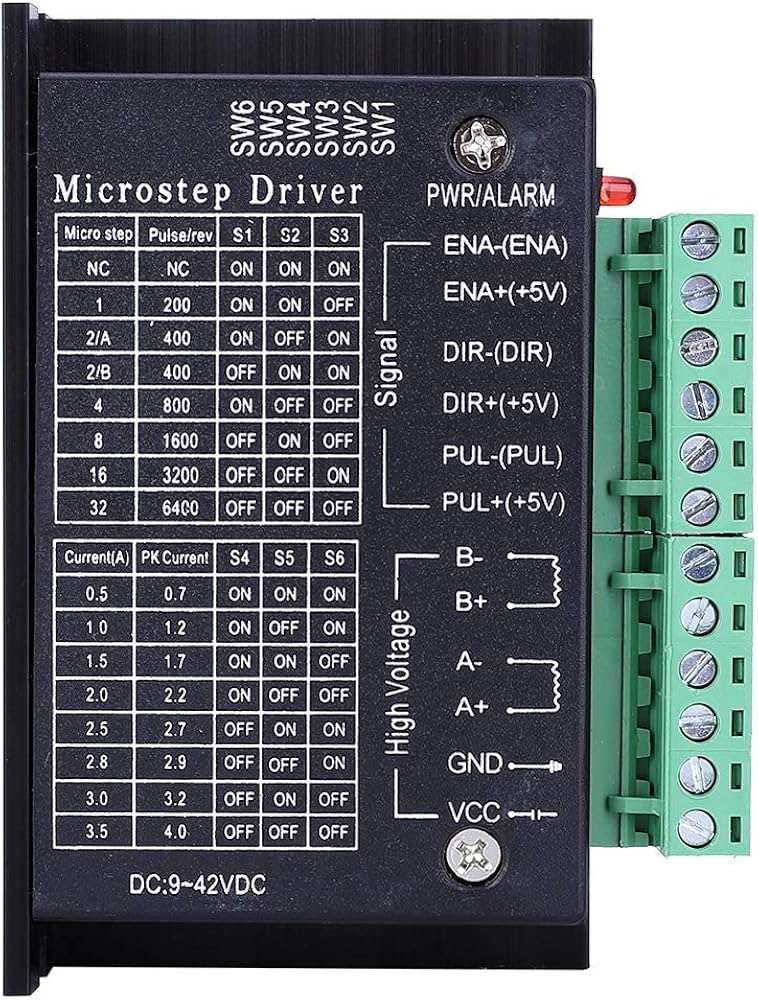
The TB6600 has a set of input and output terminals for connecting to the control system and stepper motor. Below is the pin configuration:
Input Terminals
| Pin Name | Description |
|---|---|
| PUL+ | Pulse signal input (positive terminal) |
| PUL- | Pulse signal input (negative terminal) |
| DIR+ | Direction signal input (positive terminal) |
| DIR- | Direction signal input (negative terminal) |
| ENA+ | Enable signal input (positive terminal) |
| ENA- | Enable signal input (negative terminal) |
Output Terminals
| Pin Name | Description |
|---|---|
| A+ | Stepper motor coil A positive terminal |
| A- | Stepper motor coil A negative terminal |
| B+ | Stepper motor coil B positive terminal |
| B- | Stepper motor coil B negative terminal |
Power Terminals
| Pin Name | Description |
|---|---|
| VCC | Power supply positive terminal (9V to 42V DC) |
| GND | Power supply ground terminal |
Usage Instructions
Connecting the TB6600
- Power Supply: Connect a DC power supply (9V to 42V) to the VCC and GND terminals.
- Stepper Motor: Connect the stepper motor coils to the A+, A-, B+, and B- terminals. Ensure proper wiring to avoid motor damage.
- Control Signals: Connect the PUL, DIR, and ENA terminals to a microcontroller or control system. Use the "+" and "-" terminals for differential signal inputs.
- Microstepping and Current Settings: Use the DIP switches on the TB6600 to configure microstepping and current limits according to your motor's specifications.
Example: Using TB6600 with Arduino UNO
Below is an example of how to control a stepper motor using the TB6600 and an Arduino UNO:
Wiring Diagram
- TB6600 PUL+ → Arduino Pin 2
- TB6600 DIR+ → Arduino Pin 3
- TB6600 ENA+ → Arduino Pin 4
- TB6600 PUL-, DIR-, ENA- → Arduino GND
- Stepper Motor Coils → TB6600 A+, A-, B+, B-
- Power Supply → TB6600 VCC and GND
Arduino Code
// Define control pins for the TB6600
#define PUL_PIN 2  // Pulse signal pin
#define DIR_PIN 3  // Direction signal pin
#define ENA_PIN 4  // Enable signal pin

void setup() {
  // Set control pins as outputs
  pinMode(PUL_PIN, OUTPUT);
  pinMode(DIR_PIN, OUTPUT);
  pinMode(ENA_PIN, OUTPUT);

  // Enable the driver
  digitalWrite(ENA_PIN, LOW); // LOW to enable the driver
}

void loop() {
  // Set direction of rotation
  digitalWrite(DIR_PIN, HIGH); // HIGH for one direction, LOW for the other

  // Generate pulses to move the motor
  for (int i = 0; i < 200; i++) { // 200 steps for one revolution (example)
    digitalWrite(PUL_PIN, HIGH); // Pulse HIGH
    delayMicroseconds(500);      // Adjust delay for speed control
    digitalWrite(PUL_PIN, LOW);  // Pulse LOW
    delayMicroseconds(500);      // Adjust delay for speed control
  }

  delay(1000); // Wait 1 second before reversing direction

  // Reverse direction
  digitalWrite(DIR_PIN, LOW);
  for (int i = 0; i < 200; i++) {
    digitalWrite(PUL_PIN, HIGH);
    delayMicroseconds(500);
    digitalWrite(PUL_PIN, LOW);
    delayMicroseconds(500);
  }

  delay(1000); // Wait 1 second before repeating
}
Best Practices
- Ensure the power supply voltage matches the motor's requirements.
- Set the current limit using the DIP switches to avoid overheating the motor.
- Use proper heat dissipation for the TB6600, as it can get warm during operation.
- Double-check wiring to prevent short circuits or damage to the driver.
Troubleshooting and FAQs
Common Issues and Solutions
Motor Not Moving:
- Check the power supply voltage and connections.
- Verify the control signal wiring and ensure the microcontroller is functioning.
- Ensure the enable pin (ENA) is set to LOW to activate the driver.
Motor Vibrates but Doesn't Rotate:
- Verify the stepper motor wiring. Incorrect coil connections can cause this issue.
- Check the microstepping settings on the DIP switches.
Driver Overheating:
- Ensure proper ventilation and consider adding a heatsink or fan.
- Reduce the current limit using the DIP switches.
Inconsistent Motor Movement:
- Check the pulse signal frequency and ensure it is within the supported range (up to 200 kHz).
- Verify the power supply is stable and not fluctuating.
FAQs
Q: Can the TB6600 drive unipolar stepper motors?
A: No, the TB6600 is designed specifically for bipolar stepper motors.
Q: What is the maximum step resolution supported?
A: The TB6600 supports up to 1/16 microstepping for precise motor control.
Q: Can I use a 5V control signal with the TB6600?
A: Yes, the TB6600 supports control signal voltages from 3.3V to 24V, making it compatible with most microcontrollers.
Q: How do I reset the driver after a fault?
A: Power cycle the driver by disconnecting and reconnecting the power supply. Ensure the fault condition (e.g., overheating) is resolved before restarting.
By following this documentation, you can effectively use the TB6600 stepper motor driver in your projects.