How to Use 5V PSU: Examples, Pinouts, and Specs
Introduction
A 5V Power Supply Unit (PSU) provides a stable 5-volt output to power electronic circuits and devices, ensuring consistent voltage for reliable operation. It is a fundamental component in electronics, commonly used to power microcontrollers, sensors, LEDs, and other low-voltage devices. The 5V PSU is essential for projects requiring a reliable and regulated power source.
Explore Projects Built with 5V PSU


Explore Projects Built with 5V PSU
Common Applications and Use Cases
- Powering microcontrollers like Arduino, Raspberry Pi, and ESP32.
- Supplying power to sensors, actuators, and small motors.
- Driving LED strips and displays.
- Providing a stable voltage source for breadboard prototyping.
- Charging USB-powered devices.
Technical Specifications
The following table outlines the key technical details of a typical 5V PSU:
| Parameter | Specification |
|---|---|
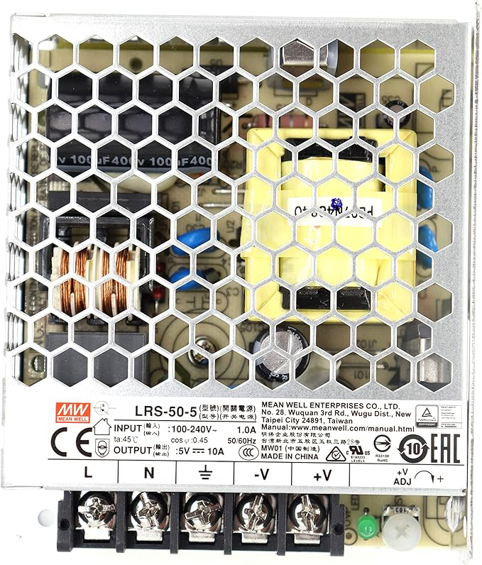
| Input Voltage Range | 100-240V AC (for AC-DC PSUs) |
| Output Voltage | 5V DC ± 0.1V |
| Output Current | 500mA to 3A (varies by model) |
| Power Rating | 2.5W to 15W |
| Efficiency | ≥ 80% |
| Ripple and Noise | ≤ 50mV |
| Protection Features | Overcurrent, Overvoltage, Short Circuit |
Pin Configuration and Descriptions
For a typical 5V PSU with a DC barrel jack or screw terminal output:
| Pin/Terminal | Description |
|---|---|
| V+ (Positive) | Provides the regulated 5V DC output. |
| V- (Negative) | Ground connection for the circuit. |
For USB-powered 5V PSUs:
| Pin | Description |
|---|---|
| VBUS | 5V DC output (positive terminal). |
| GND | Ground connection (negative terminal). |
Usage Instructions
How to Use the 5V PSU in a Circuit
- Connect the Input Power Source:
- For AC-DC PSUs, plug the unit into a standard AC outlet.
- For USB-powered PSUs, connect the USB cable to a compatible power source.
- Connect the Output Terminals:
- Attach the V+ terminal to the positive rail of your circuit.
- Attach the V- terminal to the ground rail of your circuit.
- Verify Connections:
- Double-check all connections to ensure proper polarity and avoid short circuits.
- Power On:
- Turn on the PSU (if it has a power switch) or connect it to the input power source.
Important Considerations and Best Practices
- Check Current Requirements: Ensure the PSU can supply sufficient current for all connected devices.
- Avoid Overloading: Do not exceed the PSU's maximum current rating to prevent damage.
- Use Proper Heat Dissipation: If the PSU gets warm during operation, ensure adequate ventilation.
- Polarity Matters: Always connect the V+ and V- terminals correctly to avoid damaging your circuit.
- Use Decoupling Capacitors: Add capacitors (e.g., 10µF and 0.1µF) near sensitive components to reduce noise.
Example: Using a 5V PSU with an Arduino UNO
The 5V PSU can be used to power an Arduino UNO via its VIN pin or USB port. Below is an example of connecting a 5V PSU to an Arduino UNO and controlling an LED:
Circuit Connections
- Connect the PSU's V+ to the Arduino's VIN pin (or USB port for USB-powered PSUs).
- Connect the PSU's V- to the Arduino's GND pin.
- Connect an LED to pin 13 of the Arduino with a 220-ohm resistor in series.
Arduino Code
// Simple LED Blink Example
// This code blinks an LED connected to pin 13 of the Arduino UNO.

void setup() {
  pinMode(13, OUTPUT); // Set pin 13 as an output pin
}

void loop() {
  digitalWrite(13, HIGH); // Turn the LED on
  delay(1000);            // Wait for 1 second
  digitalWrite(13, LOW);  // Turn the LED off
  delay(1000);            // Wait for 1 second
}
Troubleshooting and FAQs
Common Issues and Solutions
No Output Voltage:
- Cause: Input power is not connected or PSU is faulty.
- Solution: Verify the input power source and check the PSU's fuse or internal components.
Voltage Drops Under Load:
- Cause: PSU is overloaded or insufficient current capacity.
- Solution: Use a PSU with a higher current rating or reduce the load.
Excessive Heat:
- Cause: PSU is operating near its maximum power rating.
- Solution: Ensure proper ventilation or use a PSU with a higher power rating.
Noise or Ripple in Output:
- Cause: Poor filtering or high-frequency interference.
- Solution: Add decoupling capacitors or use a PSU with better ripple suppression.
FAQs
Q: Can I use a 5V PSU to charge my phone?
A: Yes, if the PSU has a USB output and meets the current requirements of your phone.
Q: What happens if I reverse the polarity of the connections?
A: Reversing polarity can damage your circuit. Always double-check connections before powering on.
Q: Can I use a 5V PSU to power a 3.3V device?
A: No, a 5V PSU will damage 3.3V devices. Use a voltage regulator or a step-down converter.
Q: How do I know if my PSU is overloaded?
A: Symptoms of overloading include voltage drops, excessive heat, or the PSU shutting down. Reduce the load or use a higher-rated PSU.