Cirkit Designer Logo
Cirkit Designer
Your all-in-one circuit design IDE
Home / 
Component Documentation

How to Use RYLR993_Lite: Examples, Pinouts, and Specs

Image of RYLR993_Lite
Cirkit Designer LogoDesign with RYLR993_Lite in Cirkit Designer

Introduction

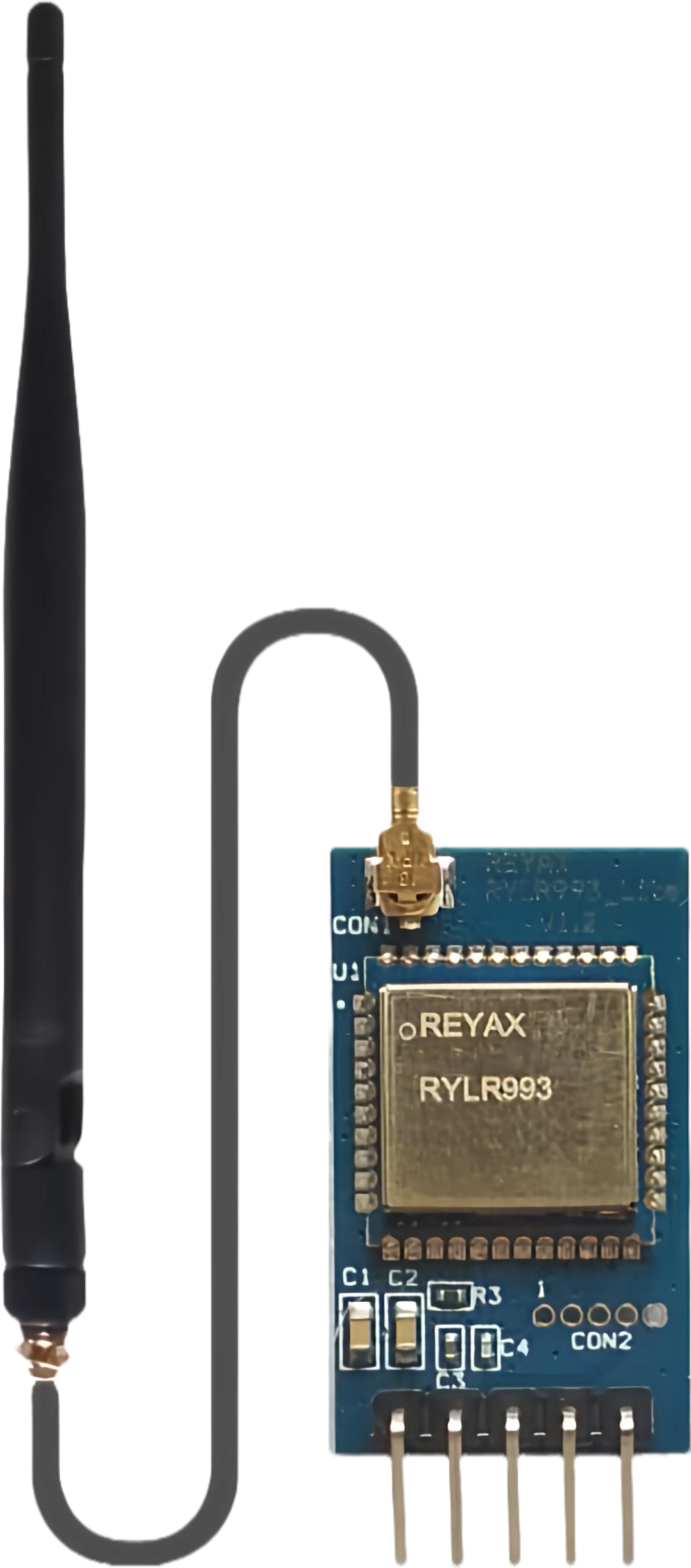
The RYLR993_Lite is a low-power, long-range LoRa transceiver module manufactured by REYAX. It is designed for wireless communication in IoT applications, offering reliable data transmission over extended distances. Operating in the 433/868/915 MHz frequency bands, the RYLR993_Lite supports multiple data rates, making it ideal for applications such as remote sensing, industrial automation, smart agriculture, and home automation.

Explore Projects Built with RYLR993_Lite

Use Cirkit Designer to design, explore, and prototype these projects online. Some projects support real-time simulation. Click "Open Project" to start designing instantly!
ESP8266 NodeMCU Wi-Fi Enabled OLED Display with RYLR896 Communication Module
Image of Smart Irrigation system Rx Side: A project utilizing RYLR993_Lite in a practical application
This circuit features an ESP8266 NodeMCU microcontroller connected to a 0.96" OLED display and an RYLR896 LoRa module. The ESP8266 communicates with the OLED via I2C protocol and interfaces with the LoRa module using UART, enabling wireless data transmission and display capabilities.
Cirkit Designer LogoOpen Project in Cirkit Designer
Arduino UNO R4 WiFi Controlled I2C LCD Display with LDR Sensor
Image of Lab4: A project utilizing RYLR993_Lite in a practical application
This circuit features an Arduino UNO R4 WiFi microcontroller connected to an I2C LCD 16x2 Screen for display purposes and a photocell (LDR) with a 220 Ohm resistor forming a voltage divider for light sensing. The Arduino is programmed to interact with these components, likely to display light intensity readings on the LCD. The I2C communication protocol is used between the Arduino and the LCD screen, while the LDR's analog voltage is read through the Arduino's A0 pin.
Cirkit Designer LogoOpen Project in Cirkit Designer
Cellular-Enabled IoT Device with Real-Time Clock and Power Management
Image of LRCM PHASE 2 BASIC: A project utilizing RYLR993_Lite in a practical application
This circuit features a LilyGo-SIM7000G module for cellular communication and GPS functionality, interfaced with an RTC DS3231 for real-time clock capabilities. It includes voltage sensing through two voltage sensor modules, and uses an 8-channel opto-coupler for isolating different parts of the circuit. Power management is handled by a buck converter connected to a DC power source and batteries, with a fuse for protection and a rocker switch for on/off control. Additionally, there's an LED for indication purposes.
Cirkit Designer LogoOpen Project in Cirkit Designer
Arduino Uno R3-Based Security System with Laser Tripwire, GSM Notification, and Motion Detection
Image of SECURITY SYSTEM: A project utilizing RYLR993_Lite in a practical application
This circuit features an Arduino Uno R3 as the central controller, interfaced with a KY-008 Laser Emitter, an LDR module, a buzzer, a Sim800l GSM module, and an MPU-6050 accelerometer/gyroscope. The Arduino controls the laser emitter and buzzer, reads analog values from the LDR, communicates with the Sim800l via serial (RX/TX), and interfaces with the MPU-6050 over I2C (SCL/SDA). The circuit is likely designed for sensing light intensity, motion detection, and communication via GSM, with the capability to emit laser light and sound alerts.
Cirkit Designer LogoOpen Project in Cirkit Designer

Explore Projects Built with RYLR993_Lite

Use Cirkit Designer to design, explore, and prototype these projects online. Some projects support real-time simulation. Click "Open Project" to start designing instantly!
Image of Smart Irrigation system Rx Side: A project utilizing RYLR993_Lite in a practical application
ESP8266 NodeMCU Wi-Fi Enabled OLED Display with RYLR896 Communication Module
This circuit features an ESP8266 NodeMCU microcontroller connected to a 0.96" OLED display and an RYLR896 LoRa module. The ESP8266 communicates with the OLED via I2C protocol and interfaces with the LoRa module using UART, enabling wireless data transmission and display capabilities.
Cirkit Designer LogoOpen Project in Cirkit Designer
Image of Lab4: A project utilizing RYLR993_Lite in a practical application
Arduino UNO R4 WiFi Controlled I2C LCD Display with LDR Sensor
This circuit features an Arduino UNO R4 WiFi microcontroller connected to an I2C LCD 16x2 Screen for display purposes and a photocell (LDR) with a 220 Ohm resistor forming a voltage divider for light sensing. The Arduino is programmed to interact with these components, likely to display light intensity readings on the LCD. The I2C communication protocol is used between the Arduino and the LCD screen, while the LDR's analog voltage is read through the Arduino's A0 pin.
Cirkit Designer LogoOpen Project in Cirkit Designer
Image of LRCM PHASE 2 BASIC: A project utilizing RYLR993_Lite in a practical application
Cellular-Enabled IoT Device with Real-Time Clock and Power Management
This circuit features a LilyGo-SIM7000G module for cellular communication and GPS functionality, interfaced with an RTC DS3231 for real-time clock capabilities. It includes voltage sensing through two voltage sensor modules, and uses an 8-channel opto-coupler for isolating different parts of the circuit. Power management is handled by a buck converter connected to a DC power source and batteries, with a fuse for protection and a rocker switch for on/off control. Additionally, there's an LED for indication purposes.
Cirkit Designer LogoOpen Project in Cirkit Designer
Image of SECURITY SYSTEM: A project utilizing RYLR993_Lite in a practical application
Arduino Uno R3-Based Security System with Laser Tripwire, GSM Notification, and Motion Detection
This circuit features an Arduino Uno R3 as the central controller, interfaced with a KY-008 Laser Emitter, an LDR module, a buzzer, a Sim800l GSM module, and an MPU-6050 accelerometer/gyroscope. The Arduino controls the laser emitter and buzzer, reads analog values from the LDR, communicates with the Sim800l via serial (RX/TX), and interfaces with the MPU-6050 over I2C (SCL/SDA). The circuit is likely designed for sensing light intensity, motion detection, and communication via GSM, with the capability to emit laser light and sound alerts.
Cirkit Designer LogoOpen Project in Cirkit Designer

Common Applications

  • IoT Networks: Enables long-range communication between IoT devices.
  • Remote Sensing: Ideal for monitoring environmental conditions in agriculture or industry.
  • Smart Cities: Used in smart lighting, parking systems, and utility metering.
  • Home Automation: Facilitates wireless control of smart devices.
  • Industrial Automation: Provides robust communication in harsh environments.

Technical Specifications

Key Technical Details

Parameter Value
Frequency Bands 433 MHz / 868 MHz / 915 MHz
Modulation Technique LoRa (Long Range)
Communication Range Up to 15 km (line of sight)
Data Rate 0.3 kbps to 37.5 kbps
Operating Voltage 2.8V to 3.6V
Operating Current 10 mA (transmit), 0.1 µA (sleep mode)
Interface UART (Universal Asynchronous Receiver-Transmitter)
Operating Temperature -40°C to +85°C
Dimensions 18 mm x 25 mm x 3 mm

Pin Configuration and Descriptions

The RYLR993_Lite module has a total of 8 pins. Below is the pinout and description:

Pin Number Pin Name Description
1 VCC Power supply input (2.8V to 3.6V)
2 GND Ground
3 TXD UART Transmit (data output)
4 RXD UART Receive (data input)
5 RESET Module reset (active low)
6 WAKE Wake-up pin for sleep mode
7 ANT Antenna connection
8 NC Not connected

Usage Instructions

How to Use the RYLR993_Lite in a Circuit

  1. Power Supply: Connect the VCC pin to a 3.3V power source and the GND pin to ground.
  2. UART Communication: Connect the TXD and RXD pins to the UART pins of a microcontroller (e.g., Arduino UNO).
  3. Antenna: Attach a suitable antenna to the ANT pin for optimal signal transmission and reception.
  4. Reset: Use the RESET pin to restart the module if needed.
  5. Wake-Up: Use the WAKE pin to bring the module out of sleep mode.

Important Considerations

  • Antenna Selection: Use a high-quality antenna tuned to the operating frequency (433/868/915 MHz) for maximum range.
  • Power Supply: Ensure a stable 3.3V power supply to avoid communication issues.
  • UART Settings: Configure the UART interface with the correct baud rate (default: 9600 bps).
  • Environmental Factors: The communication range may vary depending on obstacles, interference, and weather conditions.

Example: Connecting to an Arduino UNO

Below is an example of how to use the RYLR993_Lite with an Arduino UNO for basic communication:

Circuit Connections

RYLR993_Lite Pin Arduino UNO Pin
VCC 3.3V
GND GND
TXD Pin 10 (RX)
RXD Pin 11 (TX)
RESET Digital Pin 9

Arduino Code Example

#include <SoftwareSerial.h>

// Define RX and TX pins for SoftwareSerial
SoftwareSerial loraSerial(10, 11); // RX = Pin 10, TX = Pin 11

void setup() {
  // Initialize serial communication
  Serial.begin(9600); // For debugging via Serial Monitor
  loraSerial.begin(9600); // For communication with RYLR993_Lite

  // Send initialization command to the module
  loraSerial.println("AT+ADDRESS=1"); // Set device address to 1
  delay(100);
  loraSerial.println("AT+NETWORKID=5"); // Set network ID to 5
  delay(100);
  loraSerial.println("AT+BAND=915000000"); // Set frequency to 915 MHz
  delay(100);

  Serial.println("RYLR993_Lite initialized.");
}

void loop() {
  // Check for incoming data from the module
  if (loraSerial.available()) {
    String data = loraSerial.readString();
    Serial.println("Received: " + data); // Print received data
  }

  // Send data to the module
  if (Serial.available()) {
    String command = Serial.readString();
    loraSerial.println(command); // Send command to RYLR993_Lite
  }
}

Troubleshooting and FAQs

Common Issues and Solutions

  1. No Response from the Module

    • Cause: Incorrect UART connections or baud rate mismatch.
    • Solution: Verify the TXD and RXD connections and ensure the baud rate is set to 9600 bps.
  2. Limited Communication Range

    • Cause: Poor antenna quality or environmental interference.
    • Solution: Use a high-gain antenna and minimize obstacles between devices.
  3. Module Not Powering On

    • Cause: Insufficient or unstable power supply.
    • Solution: Ensure the power supply provides a stable 3.3V.
  4. Data Loss or Corruption

    • Cause: High noise levels or incorrect UART settings.
    • Solution: Check the UART configuration and reduce interference sources.

FAQs

  • Q: Can the RYLR993_Lite operate on 5V?
    A: No, the module requires a power supply of 2.8V to 3.6V. Use a voltage regulator if needed.

  • Q: What is the maximum communication range?
    A: The module can achieve up to 15 km in line-of-sight conditions. Obstacles and interference may reduce this range.

  • Q: How do I reset the module?
    A: Pull the RESET pin low for at least 100 ms and then release it.

  • Q: Can I use the module with other microcontrollers?
    A: Yes, the RYLR993_Lite can be used with any microcontroller that supports UART communication.


This concludes the documentation for the RYLR993_Lite. For further assistance, refer to the official datasheet or contact REYAX support.