How to Use 3 Point Terminal Block: Examples, Pinouts, and Specs
Introduction
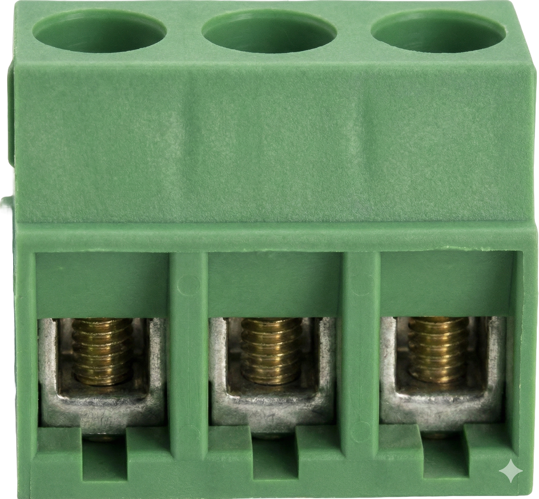
A 3 Point Terminal Block is a type of electrical connector designed to securely connect three wires or conductors. It features screw terminals that allow for easy and reliable wiring. This component is widely used in electrical and electronic systems to facilitate the distribution of power or signals. Its robust design ensures a stable connection, making it ideal for both industrial and DIY applications.
Explore Projects Built with 3 Point Terminal Block


Explore Projects Built with 3 Point Terminal Block
Common Applications and Use Cases
- Power distribution in electrical panels
- Signal routing in control systems
- Connecting sensors or actuators in automation projects
- Prototyping and testing circuits
- Use in Arduino or microcontroller-based projects for modular wiring
Technical Specifications
Below are the key technical details of a standard 3 Point Terminal Block:
| Parameter | Specification |
|---|---|
| Number of Terminals | 3 |
| Rated Voltage | 300V (varies by model) |
| Rated Current | 10A (varies by model) |
| Wire Size Compatibility | 22-12 AWG |
| Terminal Type | Screw-type |
| Mounting Style | PCB mount or DIN rail mount |
| Material | Flame-retardant plastic, metal screws |
Pin Configuration and Descriptions
The 3 Point Terminal Block does not have traditional "pins" like ICs but instead has three screw terminals. Below is a description of the terminals:
| Terminal | Description |
|---|---|
| Terminal 1 | Connects to the first wire or conductor |
| Terminal 2 | Connects to the second wire or conductor |
| Terminal 3 | Connects to the third wire or conductor |
Usage Instructions
How to Use the Component in a Circuit
- Prepare the Wires: Strip the insulation from the ends of the wires you want to connect, exposing about 5-7 mm of the conductor.
- Insert the Wires: Loosen the screws on the terminal block, insert the stripped wire ends into the corresponding terminals, and tighten the screws securely.
- Mount the Terminal Block: If the terminal block is PCB-mounted, solder it to the PCB. For DIN rail-mounted blocks, attach them to the rail.
- Connect to the Circuit: Ensure the wires are connected to the correct terminals as per your circuit design.
Important Considerations and Best Practices
- Wire Size: Ensure the wire gauge is compatible with the terminal block to avoid loose connections or damage.
- Tightening Screws: Do not overtighten the screws, as this may damage the wire or the terminal block.
- Current and Voltage Ratings: Always check the rated current and voltage of the terminal block to ensure it is suitable for your application.
- Insulation: Ensure that no exposed wire is touching adjacent terminals to prevent short circuits.
- Testing: After wiring, test the connections with a multimeter to verify continuity.
Example: Using a 3 Point Terminal Block with an Arduino UNO
The 3 Point Terminal Block can be used to connect external components, such as sensors or actuators, to an Arduino UNO. Below is an example of wiring a 3 Point Terminal Block to distribute power and ground to multiple devices.
Circuit Description
- Terminal 1: Connects to the Arduino's 5V pin.
- Terminal 2: Connects to the Arduino's GND pin.
- Terminal 3: Connects to an external device (e.g., a sensor or motor).
Sample Code
// Example code for using a 3 Point Terminal Block with an Arduino UNO
// This code demonstrates reading a sensor connected via the terminal block
// and controlling an LED based on the sensor's input.

const int sensorPin = A0;  // Sensor connected to analog pin A0
const int ledPin = 13;     // LED connected to digital pin 13

void setup() {
  pinMode(ledPin, OUTPUT);  // Set LED pin as output
  pinMode(sensorPin, INPUT); // Set sensor pin as input
  Serial.begin(9600);       // Initialize serial communication
}

void loop() {
  int sensorValue = analogRead(sensorPin); // Read sensor value
  Serial.println(sensorValue);            // Print sensor value to Serial Monitor

  if (sensorValue > 500) {                // If sensor value exceeds threshold
    digitalWrite(ledPin, HIGH);           // Turn on the LED
  } else {
    digitalWrite(ledPin, LOW);            // Turn off the LED
  }

  delay(100); // Small delay for stability
}
Troubleshooting and FAQs
Common Issues Users Might Face
- Loose Connections: Wires may come loose if the screws are not tightened properly.
- Solution: Ensure the screws are securely tightened without overtightening.
- Short Circuits: Exposed wire ends may touch adjacent terminals.
- Solution: Use properly stripped wires and ensure no exposed conductor is visible outside the terminal.
- Overheating: The terminal block may overheat if the current exceeds its rated capacity.
- Solution: Verify the current rating of the terminal block and ensure it matches your application.
- Wire Compatibility: Wires may not fit properly if they are outside the supported gauge range.
- Solution: Use wires within the specified AWG range (22-12 AWG).
FAQs
Q: Can I use a 3 Point Terminal Block for AC and DC circuits?
A: Yes, the terminal block can be used for both AC and DC circuits, provided the voltage and current ratings are not exceeded.
Q: How do I mount a PCB terminal block?
A: Align the terminal block with the PCB holes, insert the pins, and solder them securely to the PCB.
Q: Can I connect more than three wires to a 3 Point Terminal Block?
A: No, the 3 Point Terminal Block is designed for three connections. For more connections, use additional terminal blocks.
Q: Is the terminal block reusable?
A: Yes, the terminal block can be reused as long as it is not physically damaged or worn out.