How to Use MCP6004: Examples, Pinouts, and Specs
Introduction
The MCP6004 is a quad operational amplifier (op-amp) designed for low-power applications. It is ideal for battery-operated devices due to its low power consumption and wide supply voltage range. The MCP6004 offers high input impedance, low output distortion, and rail-to-rail input/output operation, making it suitable for a variety of analog signal processing tasks.
Explore Projects Built with MCP6004


Explore Projects Built with MCP6004
Common Applications
- Signal amplification in sensor circuits
- Active filters and integrators
- Voltage followers (buffer circuits)
- Analog-to-digital converter (ADC) signal conditioning
- Portable and battery-powered devices
Technical Specifications
Key Technical Details
| Parameter | Value |
|---|---|
| Supply Voltage Range | 1.8V to 6.0V |
| Supply Current (per op-amp) | 100 µA (typical) |
| Input Impedance | 10⁶ MΩ (typical) |
| Output Voltage Swing | Rail-to-rail |
| Gain Bandwidth Product | 1 MHz |
| Slew Rate | 0.6 V/µs |
| Input Offset Voltage | ±4.5 mV (maximum) |
| Operating Temperature Range | -40°C to +85°C |
| Package Options | PDIP, SOIC, TSSOP |
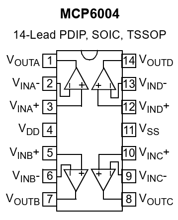
Pin Configuration and Descriptions
The MCP6004 is available in an 14-pin package. Below is the pinout and description:
| Pin Number | Pin Name | Description |
|---|---|---|
| 1 | OUT A | Output of Op-Amp A |
| 2 | IN- A | Inverting Input of Op-Amp A |
| 3 | IN+ A | Non-Inverting Input of Op-Amp A |
| 4 | VSS | Ground (Negative Power Supply) |
| 5 | IN+ B | Non-Inverting Input of Op-Amp B |
| 6 | IN- B | Inverting Input of Op-Amp B |
| 7 | OUT B | Output of Op-Amp B |
| 8 | OUT C | Output of Op-Amp C |
| 9 | IN- C | Inverting Input of Op-Amp C |
| 10 | IN+ C | Non-Inverting Input of Op-Amp C |
| 11 | VDD | Positive Power Supply |
| 12 | IN+ D | Non-Inverting Input of Op-Amp D |
| 13 | IN- D | Inverting Input of Op-Amp D |
| 14 | OUT D | Output of Op-Amp D |
Usage Instructions
How to Use the MCP6004 in a Circuit
- Power Supply: Connect the VDD pin to the positive supply voltage (1.8V to 6.0V) and the VSS pin to ground.
- Input Connections: Connect the signal to be amplified to the non-inverting (IN+) or inverting (IN-) input of the desired op-amp channel.
- Output Connections: The amplified signal will be available at the corresponding output pin (OUT A, OUT B, OUT C, or OUT D).
- Feedback Network: Use resistors, capacitors, or other components to configure the op-amp for the desired gain, filtering, or other functionality.
Important Considerations
- Power Supply Decoupling: Place a 0.1 µF ceramic capacitor close to the VDD pin to reduce noise and improve stability.
- Input Voltage Range: Ensure the input voltage stays within the supply voltage range to avoid distortion or damage.
- Load Impedance: Use a load impedance of at least 10 kΩ to ensure proper operation and avoid excessive current draw.
- Unused Op-Amps: If any of the op-amps are unused, connect their inputs to ground or a reference voltage to prevent unwanted oscillations.
Example: Connecting MCP6004 to an Arduino UNO
The MCP6004 can be used to amplify an analog signal for an Arduino UNO's ADC. Below is an example circuit and code:
Circuit Description
- Connect VDD to the Arduino's 5V pin and VSS to GND.
- Use one op-amp (e.g., Op-Amp A) to amplify a sensor signal.
- Connect the amplified output (OUT A) to an analog input pin on the Arduino (e.g., A0).
Arduino Code Example
// MCP6004 Example: Reading an amplified signal from Op-Amp A
const int analogPin = A0; // Analog pin connected to OUT A of MCP6004

void setup() {
  Serial.begin(9600); // Initialize serial communication
}

void loop() {
  int sensorValue = analogRead(analogPin); // Read the amplified signal
  float voltage = sensorValue * (5.0 / 1023.0); // Convert ADC value to voltage

  // Print the voltage to the Serial Monitor
  Serial.print("Amplified Signal Voltage: ");
  Serial.print(voltage);
  Serial.println(" V");

  delay(500); // Wait for 500ms before the next reading
}
Troubleshooting and FAQs
Common Issues and Solutions
No Output Signal:
- Verify that the power supply is connected correctly (VDD and VSS).
- Check the input signal and ensure it is within the op-amp's input voltage range.
- Ensure the feedback network is properly configured.
Distorted Output:
- Confirm that the input signal is not exceeding the supply voltage range.
- Check the load impedance; it should be at least 10 kΩ.
- Add a decoupling capacitor near the power supply pins to reduce noise.
Oscillations or Instability:
- Ensure unused op-amps have their inputs tied to ground or a reference voltage.
- Verify that the feedback network is stable and does not introduce excessive phase shift.
Low Gain or Incorrect Amplification:
- Double-check the resistor values in the feedback network.
- Ensure the op-amp is configured correctly for the desired gain (inverting or non-inverting).
FAQs
Q: Can the MCP6004 operate with a single supply voltage?
A: Yes, the MCP6004 is designed to operate with a single supply voltage as low as 1.8V.
Q: What is the maximum output current of the MCP6004?
A: The MCP6004 can source or sink up to 23 mA (typical), but it is recommended to use a load impedance of at least 10 kΩ for optimal performance.
Q: Is the MCP6004 suitable for audio applications?
A: Yes, the MCP6004's low distortion and rail-to-rail operation make it suitable for low-power audio signal processing.
Q: How do I handle unused op-amps in the MCP6004?
A: Connect the unused op-amp inputs to ground or a reference voltage to prevent oscillations.