
How to Use Adafruit INA260: Examples, Pinouts, and Specs
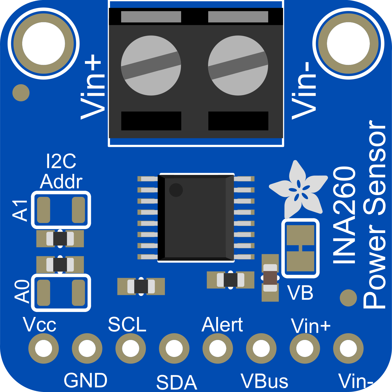
 Design with Adafruit INA260 in Cirkit Designer
Introduction
The Adafruit INA260 is a high-precision current and voltage sensor module that allows for simultaneous monitoring of current, voltage, and power through a single I2C interface. This sensor is ideal for a wide range of applications, including power supply monitoring, battery charging, energy consumption tracking, and load sensing in various electronic projects.
Explore Projects Built with Adafruit INA260
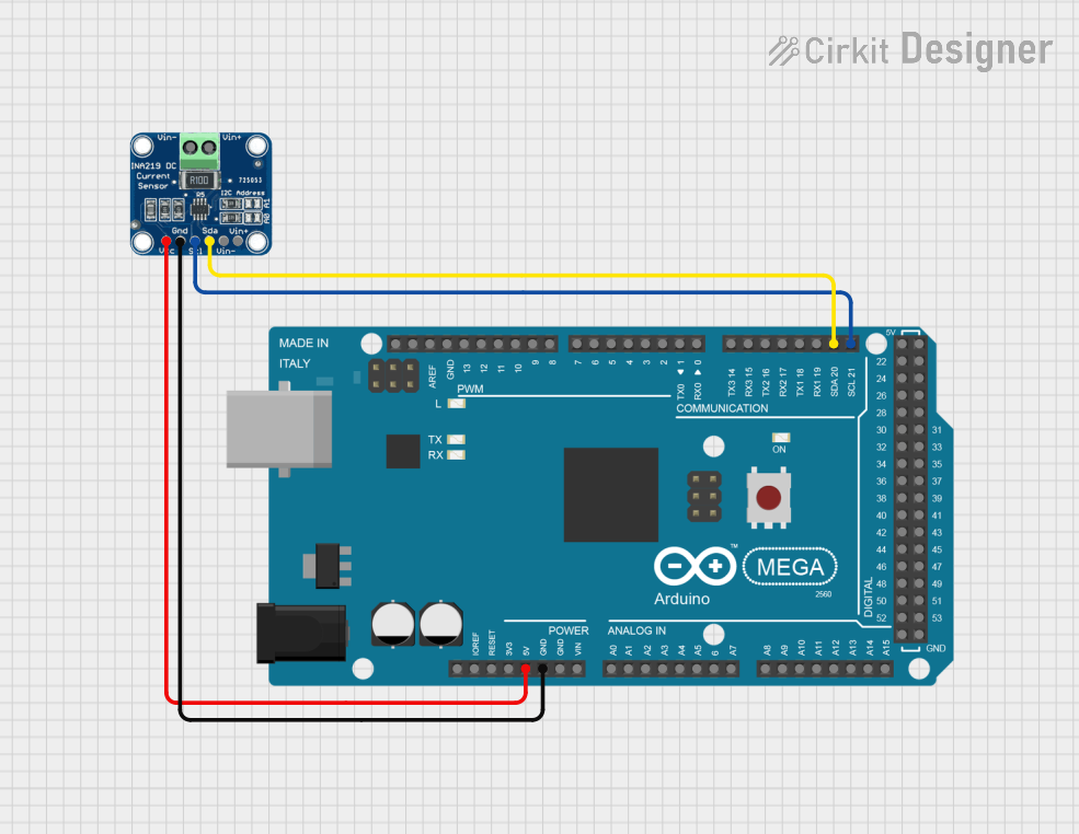
 Open Project in Cirkit Designer
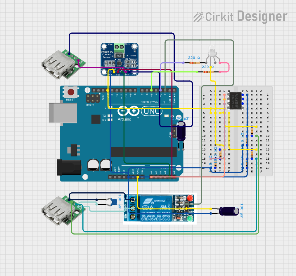
 Open Project in Cirkit Designer
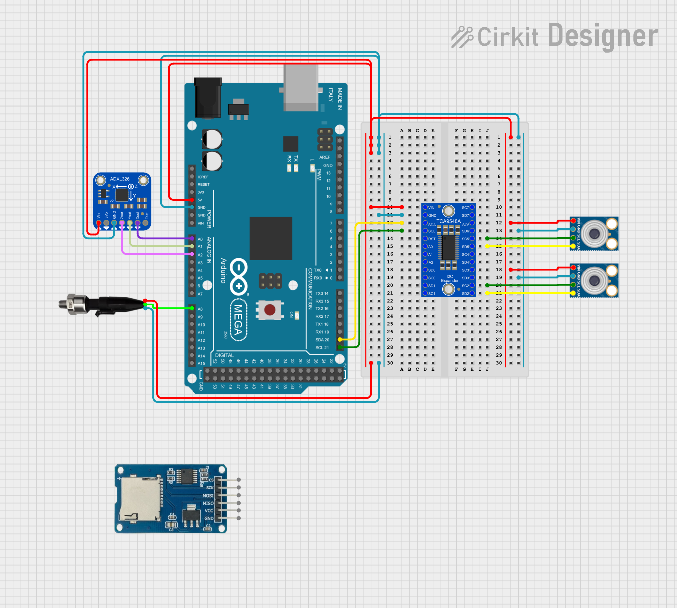
 Open Project in Cirkit Designer
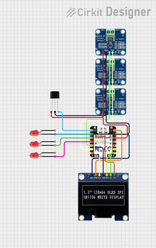
 Open Project in Cirkit Designer
Explore Projects Built with Adafruit INA260

 Open Project in Cirkit Designer
 Open Project in Cirkit Designer
 Open Project in Cirkit Designer
 Open Project in Cirkit Designer
Common Applications and Use Cases
- Power supply monitoring
- Battery chargers and management systems
- Energy consumption measurement for energy-saving systems
- Load detection and management in electronic circuits
- Portable instrumentation
Technical Specifications
Key Technical Details
- Voltage Measurement Range: 0 to 36 V
- Current Measurement Range: -15 A to +15 A
- Power Measurement Range: Up to 45 W
- Resolution:
- Voltage: 1.25 mV
- Current: 0.1 mA
- I2C Interface: Standard, Fast, and High-Speed Modes
- Operating Voltage: 3.0 V to 5.5 V
- Operating Temperature: -40°C to +125°C
Pin Configuration and Descriptions
| Pin Number | Name | Description |
|---|---|---|
| 1 | VIN+ | Voltage input, positive side of the shunt resistor |
| 2 | VIN- | Voltage input, negative side of the shunt resistor |
| 3 | GND | Ground reference for the module |
| 4 | SCL | I2C clock signal |
| 5 | SDA | I2C data signal |
| 6 | VCC | Power supply for the module (3.0 V to 5.5 V) |
| 7 | ALERT | Alert pin, configurable for various warning and limit conditions |
| 8 | ADDR | I2C address selection pin |
Usage Instructions
How to Use the Component in a Circuit
- Powering the Module: Connect the VCC pin to a 3.0 V to 5.5 V power source and the GND pin to the ground of your system.
- Current Sensing: Place the module in series with the load to measure the current flowing through it. Connect the positive side of the load to VIN+ and the negative side to VIN-.
- Voltage Sensing: The voltage across the load is measured between VIN+ and VIN-.
- I2C Communication: Connect the SCL and SDA pins to the corresponding I2C clock and data lines on your microcontroller.
- Address Selection: The ADDR pin can be connected to GND, VCC, SDA, or SCL to select one of four possible I2C addresses for the device.
Important Considerations and Best Practices
- Ensure that the current and voltage do not exceed the specified maximum ratings of the module.
- Use proper decoupling capacitors close to the module's power pins to minimize noise.
- Keep the I2C lines as short as possible to prevent signal degradation.
- Use pull-up resistors on the I2C lines if they are not already present on your microcontroller board.
Example Code for Arduino UNO
#include <Wire.h>
#include <Adafruit_INA260.h>

Adafruit_INA260 ina260 = Adafruit_INA260();

void setup() {
  Serial.begin(115200);
  // Initialize the INA260
  if (!ina260.begin()) {
    Serial.println("Couldn't find INA260 chip");
    while (1);
  }
  Serial.println("Found INA260 chip");
}

void loop() {
  Serial.print("Current: ");
  Serial.print(ina260.readCurrent());
  Serial.println(" mA");
  Serial.print("Voltage: ");
  Serial.print(ina260.readBusVoltage());
  Serial.println(" mV");
  Serial.print("Power: ");
  Serial.print(ina260.readPower());
  Serial.println(" mW");
  delay(1000);
}
Troubleshooting and FAQs
Common Issues Users Might Face
- No Data on I2C: Check connections and ensure pull-up resistors are installed. Verify that the I2C address matches the one configured by the ADDR pin.
- Inaccurate Readings: Ensure that the INA260 is properly calibrated and that the voltage and current are within the specified range.
- Device Not Found: Make sure the module is powered correctly and that the I2C lines are connected properly.
Solutions and Tips for Troubleshooting
- Double-check wiring, especially the I2C connections and the orientation of the sensor.
- Use the I2C scanner sketch to confirm the device's address on the I2C bus.
- Ensure that the power supply is stable and within the specified voltage range.
FAQs
Q: Can the INA260 measure negative current? A: Yes, the INA260 can measure current in both directions, from -15 A to +15 A.
Q: What is the maximum voltage that can be measured? A: The INA260 can measure voltages up to 36 V.
Q: How do I change the I2C address of the INA260? A: The I2C address can be changed by connecting the ADDR pin to GND, VCC, SDA, or SCL, providing four different address options.
Q: Is it possible to use multiple INA260 modules on the same I2C bus? A: Yes, you can use up to four INA260 modules on the same I2C bus by setting a unique address for each using the ADDR pin.