How to Use Pixhawk 6C: Examples, Pinouts, and Specs
Introduction
The Pixhawk 6C is an advanced flight control hardware designed for drones and other unmanned vehicles. It features a powerful processor, multiple sensor inputs, and support for various communication protocols, making it ideal for autonomous flight and complex missions. This flight controller is part of the Pixhawk ecosystem, known for its reliability, flexibility, and compatibility with open-source autopilot software such as PX4 and ArduPilot.
Explore Projects Built with Pixhawk 6C

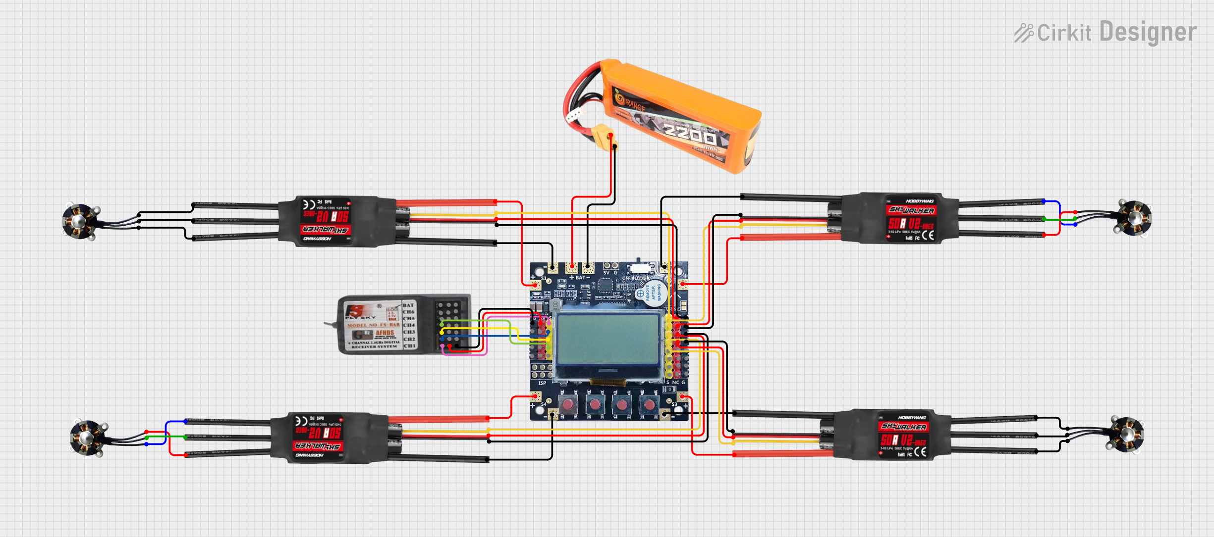
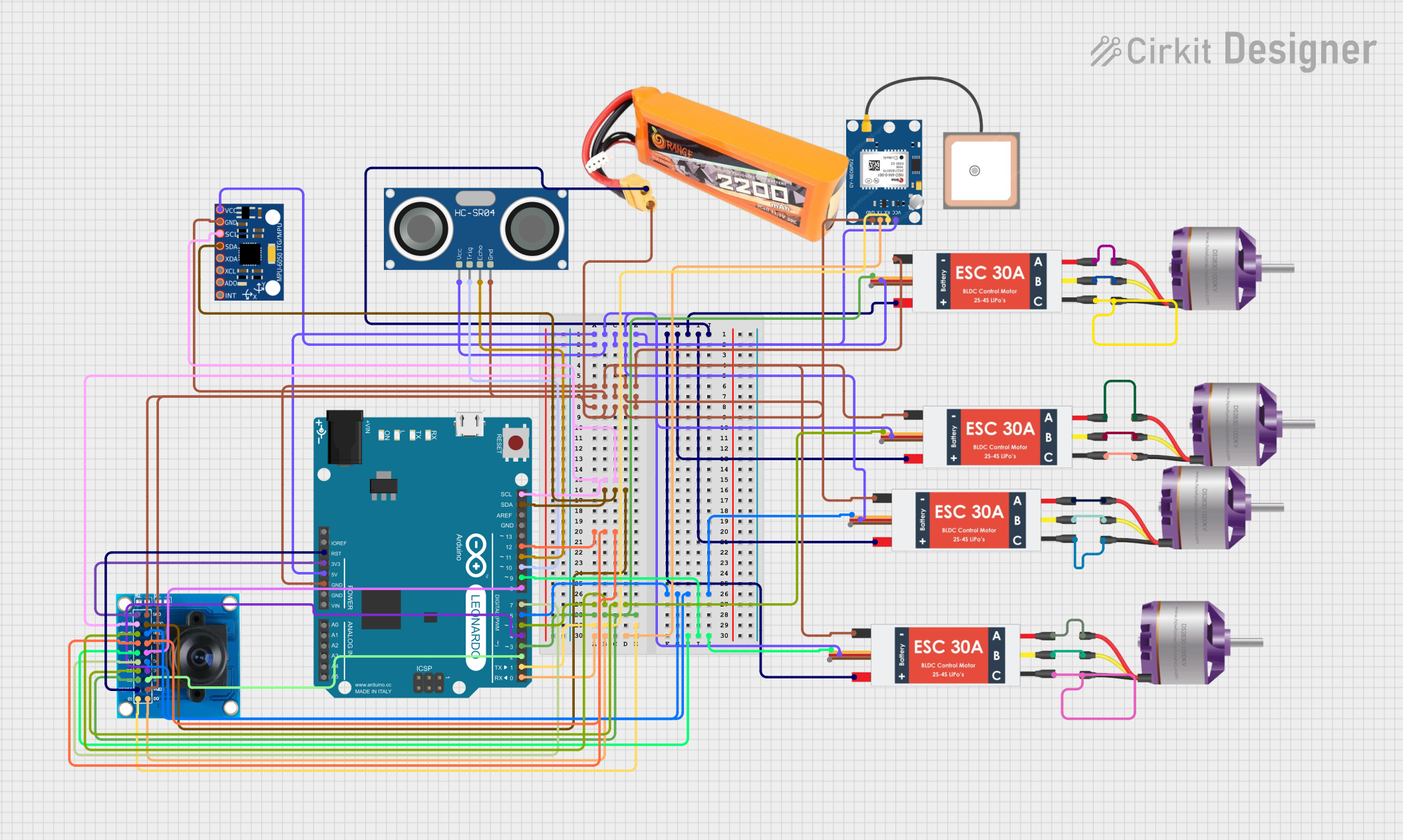
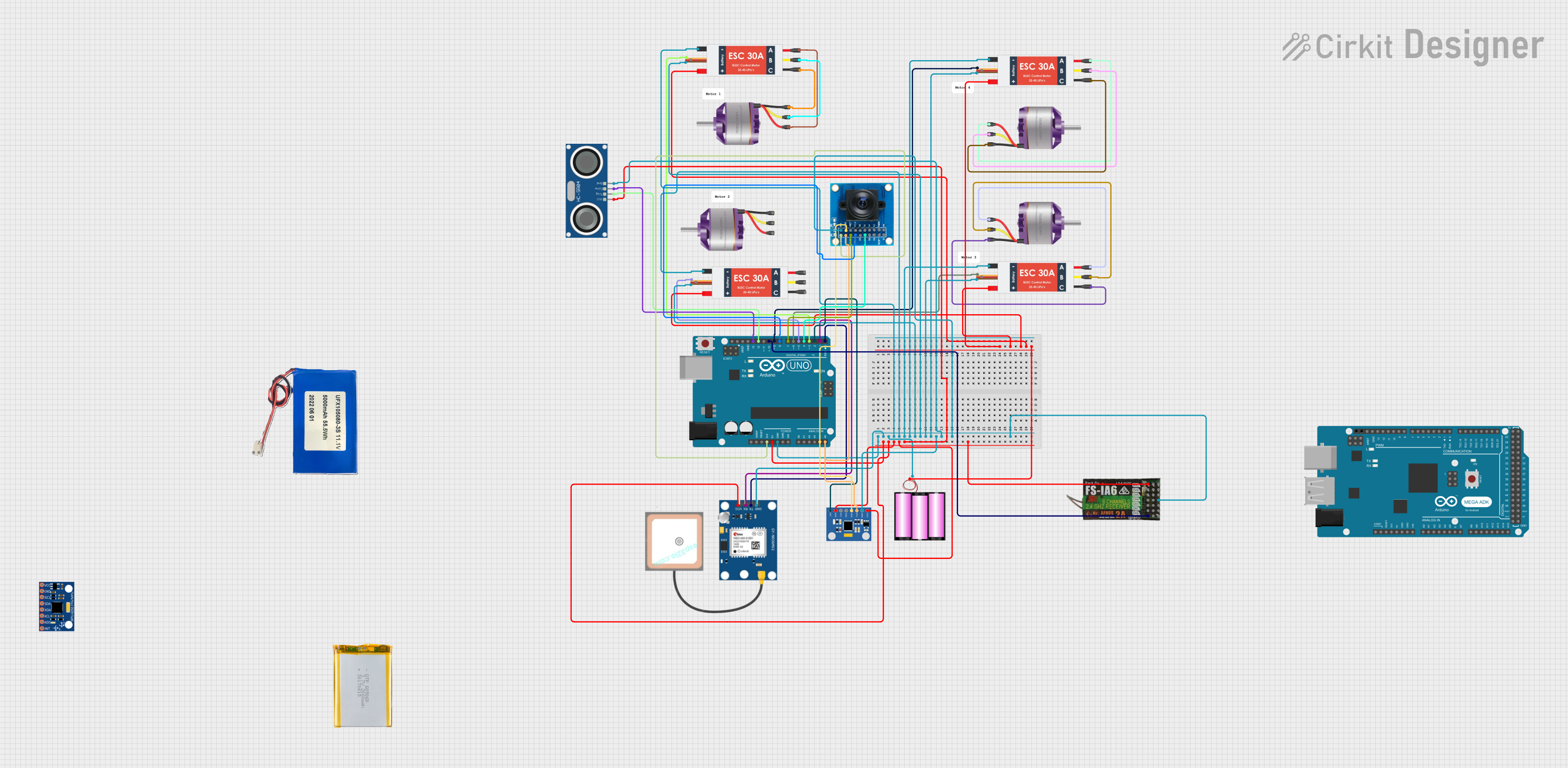
Explore Projects Built with Pixhawk 6C
Common Applications and Use Cases
- Autonomous drones for aerial photography, mapping, and surveying
- Unmanned ground vehicles (UGVs) for industrial or research purposes
- Marine vehicles such as autonomous boats or submarines
- Robotics projects requiring precise control and sensor integration
- Research and development in autonomous systems and AI
Technical Specifications
Key Technical Details
| Specification | Value |
|---|---|
| Processor | STM32H743, 32-bit ARM Cortex-M7, 480 MHz |
| IMUs (Inertial Measurement Units) | 2x IMUs (1x ICM-42688-P, 1x ICM-20948) |
| Barometer | MS5611 |
| Input Voltage Range | 4.3V to 5.4V |
| Power Supply | Redundant power inputs with power management |
| Communication Interfaces | UART, I2C, CAN, SPI, USB, DSM, SBUS, PPM |
| PWM Outputs | 8 PWM outputs |
| Dimensions | 38.5 mm x 55.5 mm x 15.5 mm |
| Weight | 15 grams |
| Operating Temperature Range | -20°C to 60°C |
| Software Compatibility | PX4, ArduPilot |
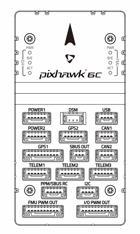
Pin Configuration and Descriptions
The Pixhawk 6C features multiple connectors for peripherals and power. Below is a summary of the key pin configurations:
Power and I/O Ports
| Pin Name | Description |
|---|---|
| POWER1 | Primary power input (4.3V to 5.4V) |
| POWER2 | Redundant power input |
| PWM OUT 1-8 | Outputs for motor ESCs or servos |
| FMU PWM IN | Input for external PWM signals |
Communication Ports
| Pin Name | Description |
|---|---|
| TELEM1 | Telemetry port 1 (UART) |
| TELEM2 | Telemetry port 2 (UART) |
| GPS | GPS module connection (UART + I2C) |
| CAN1, CAN2 | CAN bus interfaces for peripherals |
| I2C1, I2C2 | I2C interfaces for external sensors |
| USB-C | USB interface for configuration and firmware updates |
Auxiliary Ports
| Pin Name | Description |
|---|---|
| AUX1-AUX6 | Auxiliary PWM outputs |
| ADC1, ADC2 | Analog-to-digital converter inputs |
| DEBUG | Debugging interface |
Usage Instructions
How to Use the Pixhawk 6C in a Circuit
Powering the Pixhawk 6C:
- Connect a regulated power source (4.3V to 5.4V) to the
POWER1port. - Optionally, connect a backup power source to the
POWER2port for redundancy.
- Connect a regulated power source (4.3V to 5.4V) to the
Connecting Peripherals:
- Attach ESCs or servos to the
PWM OUTports. - Connect a GPS module to the
GPSport for navigation. - Use the
TELEM1orTELEM2ports to connect telemetry radios for communication with a ground control station.
- Attach ESCs or servos to the
Configuring the Flight Controller:
- Connect the Pixhawk 6C to a computer using the USB-C port.
- Install and launch a compatible ground control software (e.g., QGroundControl or Mission Planner).
- Follow the software's setup wizard to configure the flight controller, calibrate sensors, and upload firmware.
Programming Autonomous Missions:
- Use the ground control software to define waypoints and mission parameters.
- Upload the mission to the Pixhawk 6C and verify the settings.
Important Considerations and Best Practices
- Ensure all connections are secure to prevent signal loss or power interruptions during operation.
- Use shielded cables for communication ports to minimize electromagnetic interference.
- Regularly update the firmware to benefit from the latest features and bug fixes.
- Perform pre-flight checks, including sensor calibration and battery level verification.
- Avoid exposing the Pixhawk 6C to extreme temperatures or moisture.
Example Code for Arduino UNO Integration
The Pixhawk 6C can communicate with an Arduino UNO via UART. Below is an example code snippet for reading telemetry data:
#include <SoftwareSerial.h>

// Define RX and TX pins for UART communication
SoftwareSerial pixhawkSerial(10, 11); // RX = pin 10, TX = pin 11

void setup() {
  // Initialize serial communication
  Serial.begin(9600); // For debugging via Serial Monitor
  pixhawkSerial.begin(57600); // Pixhawk telemetry baud rate

  Serial.println("Pixhawk 6C UART Communication Initialized");
}

void loop() {
  // Check if data is available from Pixhawk
  if (pixhawkSerial.available()) {
    // Read and print data from Pixhawk
    String telemetryData = "";
    while (pixhawkSerial.available()) {
      telemetryData += (char)pixhawkSerial.read();
    }
    Serial.println("Telemetry Data: " + telemetryData);
  }

  // Add a small delay to avoid flooding the Serial Monitor
  delay(100);
}
Troubleshooting and FAQs
Common Issues and Solutions
Issue: Pixhawk 6C does not power on.
- Solution: Verify that the power source is within the specified voltage range (4.3V to 5.4V). Check the connections to the
POWER1andPOWER2ports.
- Solution: Verify that the power source is within the specified voltage range (4.3V to 5.4V). Check the connections to the
Issue: GPS module is not detected.
- Solution: Ensure the GPS module is properly connected to the
GPSport. Check for loose or damaged cables. Verify that the GPS module is compatible with the Pixhawk 6C.
- Solution: Ensure the GPS module is properly connected to the
Issue: Telemetry data is not received on the ground control station.
- Solution: Confirm that the telemetry radio is connected to the correct port (
TELEM1orTELEM2). Check the baud rate settings in the ground control software.
- Solution: Confirm that the telemetry radio is connected to the correct port (
Issue: Motors or servos do not respond.
- Solution: Verify that the ESCs or servos are connected to the correct
PWM OUTports. Ensure the motor outputs are configured in the ground control software.
- Solution: Verify that the ESCs or servos are connected to the correct
FAQs
Q: Can the Pixhawk 6C be used with ArduPilot?
- A: Yes, the Pixhawk 6C is fully compatible with ArduPilot.
Q: How do I update the firmware on the Pixhawk 6C?
- A: Connect the Pixhawk 6C to a computer via USB-C, open the ground control software, and follow the firmware update instructions.
Q: What is the maximum number of PWM outputs supported?
- A: The Pixhawk 6C supports up to 8 PWM outputs for motors or servos.
Q: Is the Pixhawk 6C compatible with LiDAR sensors?
- A: Yes, LiDAR sensors can be connected via I2C, UART, or CAN interfaces, depending on the sensor model.